Rotation Table
The Rotation Table settings panel lets you connect and control a motorized turntable for automated polar measurements. Once connected, the table integrates with the IR Management window to drive the auto-scan feature, which rotates the speaker and captures impulse responses at each angle without any manual intervention.
Requires a valid LinFIR license. All rotation table features — connection, manual jog controls, position dial, and auto-scan — are available to license holders only. Without a valid license the Settings → Rotation Table tab is displayed grayed out.
Supported Hardware
LinFIR supports two families of rotation table controllers:
| Controller | Interface | Detection | Example hardware |
|---|---|---|---|
| Pololu Tic (T500, T834, T825, T249, 36v4) | USB (native) | Automatic via USB VID/PID | Any stepper with a Tic controller |
| GRBL (Arduino) | USB-serial | Serial port enumeration | Audiomatica Medusa, DIY Arduino build |
Pololu Tic controllers are identified automatically by their USB vendor ID. GRBL boards appear as serial ports; LinFIR probes them with a status query to confirm the firmware.
Accessing the Settings
Open Edit → Settings (or Cmd+, / Ctrl+,) and select the Rotation Table tab.
Connecting a Table
1. Port and Baud Rate
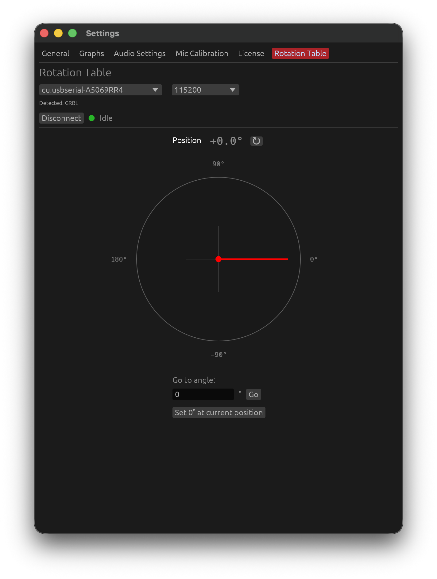
LinFIR scans available ports each time the settings panel is drawn. Use the port combobox to select the device; the detected controller type is shown next to each entry (e.g. COM3 — GRBL or /dev/cu.usbmodem… — Pololu Tic).
For GRBL boards, choose the baud rate that matches your firmware (typically 115200). Pololu Tic controllers connected over USB do not use a baud rate.
A small label below the combobox confirms the auto-detected type:
Detected: GRBL
or
Detected: Pololu Tic
2. Connect / Disconnect
Click Connect to open the connection. LinFIR probes the controller and updates the detected type if needed. A status indicator appears to the right of the Disconnect button:
| Dot colour | Meaning |
|---|---|
| 🟢 Green | Connected — table idle |
| 🟡 Yellow | Table is moving |
Click Disconnect to cleanly close the serial/USB connection.
Position Dial
After connecting, a dial shows the current table angle:
- Red needle points to the current position (−180° to +180°)
- Cardinal labels: 0°, 90°, 180°, −90°
- ↻ button — sends a position query and refreshes the display immediately
The angle is updated automatically whenever the table moves or reports its position.
Manual Controls
GRBL Controllers
| Control | Description |
|---|---|
| Go to angle field + Go | Sends G1X<angle>F360 — moves to the specified angle at 360 deg/min |
| Set 0° at current position | Sends G92X0 — redefines the current position as the zero reference |
LinFIR reads the GRBL angle as the work position (machine position minus the
G92offset), so after Set 0° the displayed angle and the auto-scan targets count from the new zero, with GRBL 1.1 as with older firmware.
The Go button is disabled while the table is moving.
Pololu Tic Controllers
| Control | Description |
|---|---|
| Range — min / max steps | Defines the microstep positions that correspond to −180° and +180°. Drag-adjust or type a value. |
| Steps/° info label | Computed from the range: (max − min) / 360. Shown in grey below the range fields. |
| Go to angle field + Go | Converts the angle to microsteps using the range and sends SET_TARGET_POSITION (energizing the motor first if it isn’t) |
| Set 0° at current position | Sends HALT_AND_SET_POSITION 0 — resets the current position to 0 steps / 0° |
| Energize / De-energize | Toggles the stepper driver power. The button names the action: green Energize while the motor turns freely, red De-energize while it holds. A Go energizes the motor first if needed, and the button follows. |
| De-energize motor after auto-scan | Toggle (off by default). When enabled, the motor is automatically de-energized once an auto-scan finishes returning to 0° — see Auto-Scan with a Rotation Table. |
Tic range calibration: Set the range so that the min and max step values span a full 360° rotation. For example, if your Tic is configured for 200 steps/rev × 16 microsteps = 3200 steps/rev, use −1600 to +1600 for ±180°.
Workflow: Manual Polar Measurement
If you prefer to position the table by hand and measure angle-by-angle without auto-scan:
- Connect the table in Settings → Rotation Table.
- Open the IR Management window for a driver.
- Use Go to angle to move the table to the desired off-axis angle.
- Set the Measurement angle field in the IR window to match.
- Click 🎤 Measure to capture.
- Repeat for each angle.
For a fully automated workflow, see Auto-Scan with a Rotation Table in the Sweep Measurements documentation.
Tips and Best Practices
- Set zero before scanning — use “Set 0° at current position” with the speaker pointing directly at the microphone, so 0° = on-axis.
- Always capture on-axis (0°) first — LinFIR requires a 0° reference before allowing off-axis measurements. If 0° is in the scan range it will be measured first automatically.
- Use a timing reference — for accurate phase relationships between angles, configure an Electric (loopback) or Acoustic timing reference in Audio Settings. This is critical for Directivity Analysis.
- Keep the mic at constant distance and height for all angles.
- Note where the rotation axis is relative to the front baffle (depth, and any sideways offset): if it isn’t at the baffle, enter those offsets under the measurement lists of the IR Management window - see Rotation Center Correction.
- 10° step or finer gives good sonogram and DI resolution. 5° is ideal.
- For the Pololu Tic, calibrate the step range carefully: a wrong range shifts all angle positions.
Troubleshooting
| Symptom | Likely cause | Fix |
|---|---|---|
| No port detected | Device not connected or driver missing | Plug in, install drivers, click away and back to refresh |
| “Auto-scan: rotation table timed out” | Table didn’t reach target in 30 s | Check wiring, reduce load, increase motor current |
| Table moves but angle stays 0° | Tic range is 0 (min = max) | Set correct min/max steps in Settings → Rotation Table |
| GRBL: table doesn’t respond to “Go” | Wrong baud rate | Try 9600 or 115200; match your firmware setting |
| Auto-scan skips some angles | Those angles already have a measurement | Delete existing measurements at those angles first |
Related Documentation
- Directivity Analysis — using polar measurements for DI and sonograms
- Sweep Measurements — sweep parameters and capture workflow
- Audio Setup — timing reference configuration