Sweep Measurements
LinFIR features a built-in exponential sine sweep generator for impulse response capture. This system provides high-quality measurements with automatic quality validation.
Overview
The sweep measurement system generates an exponential sine sweep that excites the system across a specified frequency range. After playback and recording, deconvolution with the inverse sweep extracts the impulse response.
Accessing Sweep Controls
Sweep controls are located in the IR Management window:
- To open the window: Driver → Manage IR
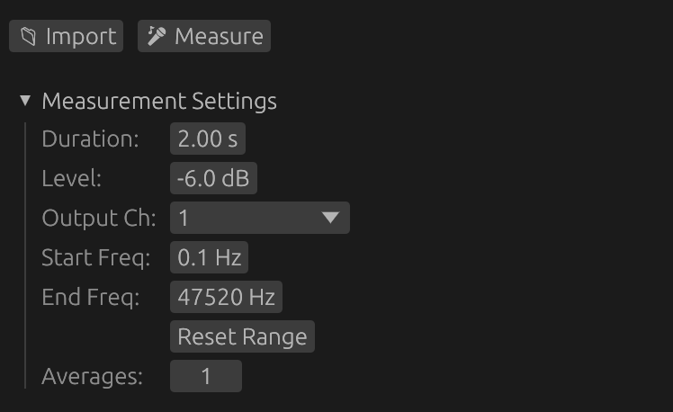
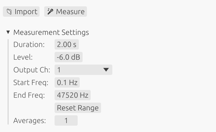
- Section: Measurement Settings
- Start button: 🎤 Measure
Sweep Parameters
⚠️ Safety Warning
Low frequency content can damage small drivers:
- Sweeps starting below 100 Hz contain high-energy bass content
- Never measure unprotected tweeters or midrange drivers with full-range sweeps
- High excursion at low frequencies can cause mechanical damage or voice coil failure
- For tweeters: Use start frequency >1000 Hz
- For midrange: Use start frequency >200-500 Hz (depending on driver specs)
- Always verify your driver’s rated frequency range before measurement
When measuring individual drivers, adjust the start frequency to match the driver’s safe operating range.
Important note on driver protection methods:
If you use an external high-pass filter (physical or DSP) to protect a driver during measurement instead of adjusting the sweep start frequency, be aware that:
- The filter will affect the phase response and group delay of the measurement
- This phase shift will be captured in the impulse response
- If you later remove or change the protection filter, the driver alignment will be incorrect
- Recommendation: Protect drivers by setting the appropriate sweep start frequency rather than using external filters
- This ensures accurate phase and timing measurements without filter-induced artifacts
Duration
Length of the sweep signal in seconds.
- Range: 1 to 15 seconds
- Shorter (1-3s): Faster measurements, lower frequency resolution, reduced harmonic distortion accuracy
- Longer (5-15s): Better low-frequency resolution, improved SNR, better harmonic distortion measurement
- Recommended: 5-7 seconds for full-range measurements
Benefits of longer sweeps:
- Improved signal-to-noise ratio for harmonic distortion analysis
- More reliable detection and measurement of weak harmonics
- Better frequency resolution in the bass region
⚠️ Important: Longer sweeps deliver more energy to the driver at low frequencies because exponential sweeps spend more time in the bass region. For drivers with limited excursion capability, longer sweeps may require:
- Raising the start frequency to avoid the lowest frequencies
- Reducing the sweep level (amplitude) to limit excursion
- Monitoring the driver during measurement to ensure it doesn’t bottom out
Amplitude
Output level of the sweep signal.
- Range: -50 to 0 dB
- Purpose: Control the acoustic level of the measurement
- Typical: -12 to -6 dB for moderate levels
- Maximum (0.0): Full digital scale output
Adjust amplitude based on driver sensitivity and desired measurement level. Too low may result in poor SNR; too high may cause clipping, distortion or damage.
Start Frequency
Cutoff frequency for the 4th-order Butterworth high-pass filter applied to the sweep for driver protection.
- Default: 1 Hz (captures near-DC response)
- Range: 1 Hz to 20 kHz
- Full-range: 20 Hz (typical for full-bandwidth measurements)
- Subwoofers: 10-20 Hz for low-frequency drivers
- Tweeters: >1000 Hz for high-frequency analysis only (protect from low frequency damage)
- Midrange: >200-500 Hz depending on driver specifications
Understanding the Butterworth Filter Protection
LinFIR applies a 4th-order Butterworth high-pass filter to the sweep signal with cutoff frequency fc = Start Frequency. This provides:
- Attenuation at cutoff: -3 dB at the Start Frequency
- Roll-off below cutoff: -24 dB/octave (deterministic, frequency-independent)
- Minimal pre-ringing: Butterworth maximally-flat passband characteristic
- Continuous protection: Applied across the entire sweep duration
⚠️ Critical positioning guideline:
Because of the -3 dB attenuation at the cutoff frequency, set Start Frequency slightly below your desired passband start, but always above driver safety limits:
- Example: For 80 Hz passband → set Start Frequency to 60-70 Hz
- This accounts for the -3 dB attenuation while ensuring full response in the desired band
- For tweeters: position above resonance frequency (fs) to avoid damage
- For woofers: set at a frequency that limits excursion to safe levels
⚠️ Important: Setting the start frequency too low for small drivers can cause mechanical damage. Always verify your driver’s rated frequency range and adjust accordingly.
For full-range measurements of complete speaker systems, 20 Hz is appropriate. For individual driver measurements, adjust to the driver’s safe operating range.
High Frequency (Automatic)
The high frequency limit is automatically calculated to optimize harmonic distortion measurement quality.
- Calculation: Based on sample rate - set to 1/48 octave before Nyquist frequency
- Range: Typically ~23.5 kHz at 48 kHz sample rate, ~47 kHz at 96 kHz
- Display: The actual calculated frequency is shown in the UI (read-only)
- Optimization: Ensures best separation and detectability of harmonic components (H2-H4)
Why automatic? The high frequency is chosen to provide optimal spacing between the fundamental and its harmonics in the time domain, ensuring accurate distortion measurement. Manual adjustment is not necessary and could compromise measurement quality.
Reset Start Freq Button
Quickly restore the start frequency to its default value:
- Action: Sets Start Freq to default frequency (configured in Audio Settings)
- Use: Return to default start frequency after using restricted frequency ranges for driver protection
Driver Protection and Automatic Windowing
LinFIR applies a sophisticated combination of 4th-order Butterworth high-pass filtering and frequency-domain cosine windowing to protect drivers while ensuring clean measurements.
Butterworth High-Pass Filter for Driver Protection
A 4th-order Butterworth high-pass filter with cutoff frequency fc = Start Frequency is continuously applied across the entire sweep for deterministic driver protection:
Filter Characteristics:
- Cutoff frequency (fc): Set by the Start Frequency parameter
- Attenuation at fc: -3 dB (Butterworth characteristic)
- Roll-off: -24 dB/octave below cutoff (4th order)
- Pre-ringing: Minimal (Butterworth provides best balance)
Why Butterworth?
- Provides deterministic, frequency-independent protection slope
- Minimal pre-ringing compared to steeper filters
- Smooth passband without ripple
- Predictable behavior for all driver types
Protection Mechanism:
- Exponentially reduces energy below the cutoff frequency
- Protects tweeters from low-frequency voltage (thermal damage)
- Limits woofer excursion at sub-bass frequencies (mechanical damage)
- Applied in frequency domain for continuous, artifact-free protection
Understanding the Need for Windowing
When a sweep signal starts or ends abruptly at specific frequencies, it creates discontinuities in the time domain. These discontinuities manifest as Gibbs oscillations in the frequency domain near sharp cutoffs.
These artifacts are not physical - they’re mathematical consequences of abrupt spectral transitions and can mask real acoustic behavior.
How Automatic Windowing Works
LinFIR combines the Butterworth filter with smooth cosine windowing at the boundaries:
Low-Frequency: Butterworth + Cosine Fade-In:
- Butterworth filter (fc = Start Frequency) provides continuous -24 dB/octave protection
- First 1/8 octave uses cosine taper combined with Butterworth to force clean 0 dB at sweep start
- Smooth transition eliminates pre-ringing artifacts
- Combined protection: cosine windowing × Butterworth filtering
High-Frequency Fade-Out:
- Begins at the automatically calculated high frequency (1/48 octave before Nyquist)
- Gradually decreases amplitude using a cosine taper
- Physical sweep extends up to 1/96 octave before Nyquist frequency
- Optimized to maximize harmonic distortion SNR
Adaptive Behavior:
- Fade-out is always applied for optimal high-frequency behavior
- This ensures the sweep always covers its full intended bandwidth with continuous protection
Benefits of Combined Protection
Driver Safety:
- Deterministic -24 dB/octave roll-off below Start Frequency
- Continuous protection without sudden energy changes
- Suitable for all driver types with appropriate frequency selection
Clean Impulse Responses:
- Well-defined peaks without oscillations
- Minimal pre-ringing and post-ringing
- Accurate representation of system behavior
Optimized for Distortion Analysis:
- High frequency chosen to maximize harmonic separation
- Better signal-to-noise ratio for harmonic distorsion detection
No Configuration Required:
- Works optimally for all measurement scenarios
- Eliminates need for user windowing decisions
- Consistent, predictable behavior
Best Practices for Frequency Range Selection
Start Frequency: Driver Protection
The Start Frequency is critical for protecting drivers from damage. Loudspeakers can be damaged by two mechanisms:
1. Over-excursion (mechanical damage)
- Occurs when the cone reaches its physical limits and “bottoms out”
- Results in distortion, mechanical stress, and potential permanent damage
- Most critical for medium to large woofers with high motor force
2. Voice coil overheating (thermal damage)
- Low frequencies behave like DC current, causing excessive heat buildup
- Most critical for midrange drivers and tweeters
- Sending bass frequencies to a tweeter is equivalent to feeding it DC current, which can burn the voice coil
- Small voice coils have limited thermal mass and dissipate heat poorly
Recommended approach by driver type:
Woofers and Subwoofers:
- Adjust Start Frequency to avoid over-excursion
- Use driver simulations to predict excursion limits (e.g., VituixCAD, WinISD)
- Start frequency should be below or at the driver’s resonance frequency for accurate measurement
- Example: 12“ woofer with 15mm Xmax → start at 20-30 Hz to avoid mechanical limits
Tweeters:
- Place Start Frequency well above the driver’s resonance frequency
- Avoid exciting the resonance peak which causes extreme excursion and heat
- Must still measure the useful passband including the crossover region
- Example: Tweeter with 800 Hz resonance and 2 kHz crossover → start at 1000-1500 Hz
- This captures the crossover transition while protecting against resonance excitation
Midrange drivers:
- Balance between capturing low-frequency rolloff and avoiding resonance excitation or over-excursion
- Typically start 100-300 Hz below the intended crossover frequency
- Monitor excursion if measuring near resonance frequency
- Example: Midrange crossing at 500 Hz with 200 Hz resonance → start at 300-400 Hz
General rule:
- Always verify your driver’s specifications before measurement
- When in doubt, start conservative (higher frequency) and lower gradually while monitoring
Starting a Measurement
Measure Button (🎤 Measure)
Clicking the 🎤 Measure button initiates the sweep measurement process.
Default behavior (confirmation enabled):
- Click 🎤 Measure
- Confirmation dialog appears with warnings:
- Check microphone and speaker positioning
- Set appropriate gain levels to avoid clipping
- The sweep will be audible
- Windows-specific timing warning (if applicable)
- Click Start Measurement to proceed or Cancel to abort
- Sweep plays and records automatically
- IR is processed and validated
Direct mode (confirmation disabled):
- Measurement starts immediately when clicking 🎤 Measure
- No confirmation dialog shown
- Useful for quick repeated measurements
Disabling Confirmation Dialog
To disable the confirmation dialog:
- Open Settings (Cmd/Ctrl + ,)
- Navigate to Audio Settings
- Enable “Skip confirmation dialog” option
- Measurements will now start immediately
Warning: Disabling confirmation means sweeps start instantly. Ensure your setup is ready before clicking the button to avoid unexpected loud sweeps.
Stopping a Measurement
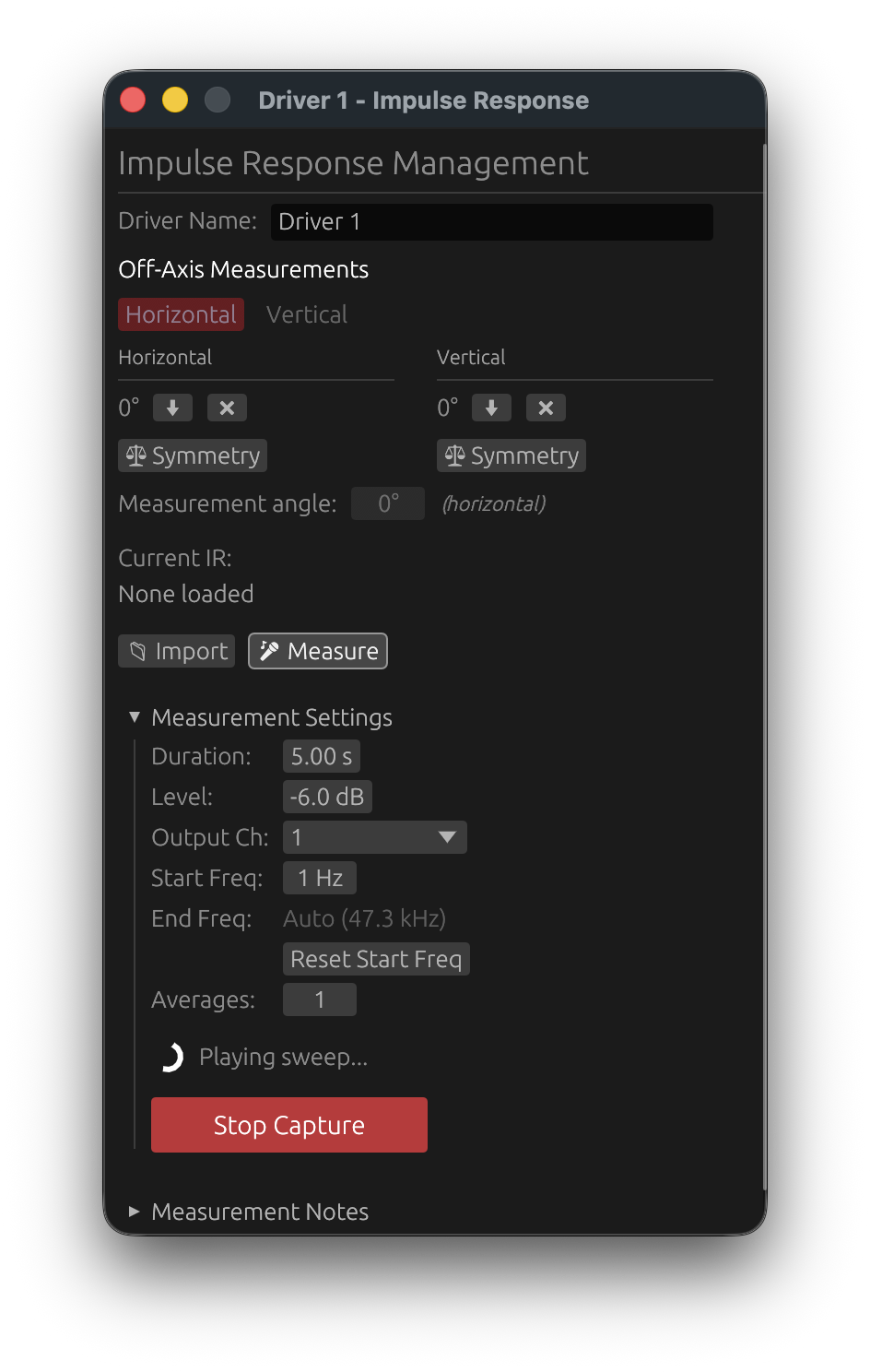
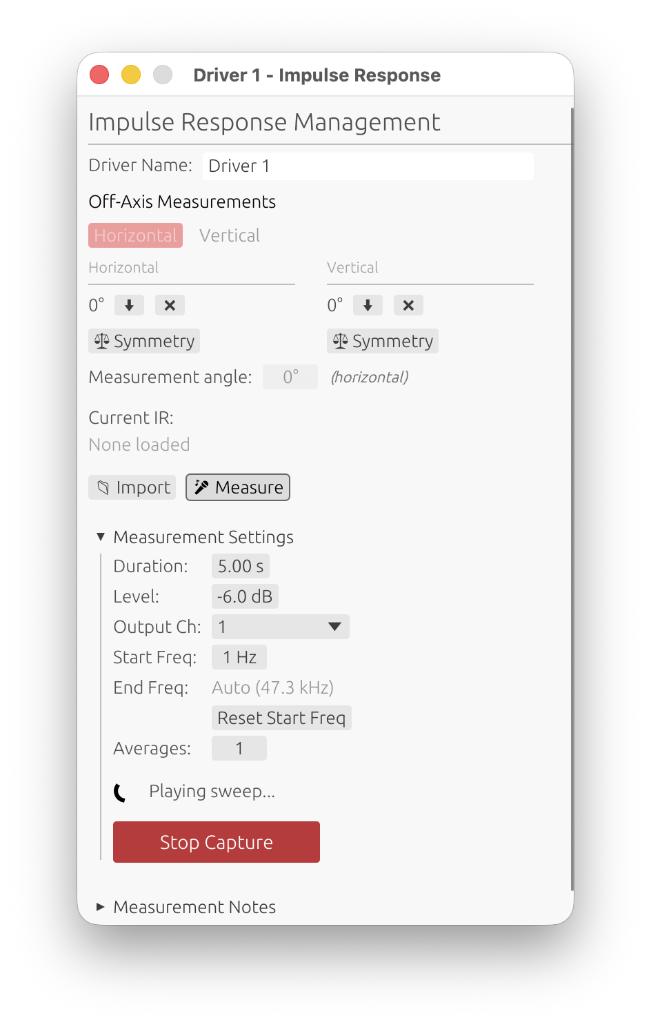
Emergency Stop
You can interrupt a sweep at any time during capture:
- Stop Capture button: Click the red button that appears during measurement
- Spacebar: Press the spacebar key for instant interruption
When to use emergency stop:
- Incorrect parameters: Realized the frequency range or level is inappropriate for the driver
- Excessive gain: Input signal is clipping or distorting
- Driver protection: Driver showing signs of stress (unusual sounds, excessive excursion)
- Environmental issues: Unexpected noise or interference occurred
The measurement will stop immediately when interrupted. You can then adjust parameters and start a new measurement.
Automatic Stop on Clipping
LinFIR monitors the input signal in real time during the entire sweep and will automatically cancel the measurement the moment clipping is detected — without waiting for the sweep to finish.
What happens:
- The input callback continuously tracks the peak level of every audio buffer
- As soon as any sample reaches digital full-scale (±1.0), the sweep is immediately faded out and stopped
- A notification toast identifies the cancellation as clipping-triggered
Toast messages:
- “Measurement cancelled: clipping detected! Reduce the output level or input gain and try again.” — clipping occurred on the main measurement channel
- “Measurement cancelled: clipping on the timing reference channel! Reduce the timing reference output level.” — clipping occurred on the timing reference channel (Electric or Acoustic mode); detected in the first ~1.2 s of the sweep, before the main sweep begins
Why this matters:
- Without real-time detection, clipping is only discovered at the end of the sweep after wasting the full measurement duration
- Immediate stop prevents unnecessary acoustic exposure of the driver to a potentially damaging clipped signal
- The automatic stop uses the same graceful fade-out as the manual Stop Capture button — no abrupt clicks
What to do:
- Reduce the audio interface input gain
- Lower the sweep amplitude
- Move the microphone farther from the driver
- For timing reference clipping: lower the timing reference output level in Audio Settings
Automatic Early Stop on Weak Timing Reference Signal
When a timing reference is active (Electric or Acoustic mode), LinFIR checks the level recorded on the timing reference channel shortly after the chirp ends, and cancels automatically if the signal was too weak to be reliable.
What happens:
- During the chirp window, the peak level on the timing reference input channel is continuously tracked
- After the end of the chirp, the accumulated peak is evaluated
- If the peak never exceeded −25 dBFS, the measurement is cancelled immediately (before the main sweep even begins)
- Toast message: “Measurement cancelled: timing reference signal too low (X.X dBFS < −25 dBFS). Check the timing reference channel connection and level.”
Why this matters:
- A weak timing reference signal makes latency detection unreliable or impossible
- Catching the problem immediately — before the full sweep — avoids wasting the measurement time
What to do:
- Check that the timing reference channel is connected correctly
- Increase the timing reference output level in Audio Settings
- For Acoustic mode, verify that the microphone can capture the high-frequency chirp (5–20 kHz)
Automatic Early Stop on Low Signal (Multi-Average)
When a measurement is configured with 2 or more averages, LinFIR checks the signal level at the end of the first sweep — before the second sweep begins — and cancels automatically if the signal was too weak.
What happens:
- During the first sweep, the peak input level is continuously tracked
- ~200 ms into the post-sweep silence (after the sweep signal has ended), the accumulated peak is evaluated
- If the peak never exceeded −25 dBFS, the measurement is cancelled before the second average starts
- Toast message: “Measurement cancelled: signal too low on first sweep (< −25 dBFS). Increase input gain or move the microphone closer.”
Why this matters:
- A low-level signal produces a poor signal-to-noise ratio; averaging more sweeps will not fix it
- Stopping after the first sweep avoids wasting time on subsequent averages that would yield unusable results
What to do:
- Increase the audio interface input gain
- Move the microphone closer to the driver
- Increase the sweep amplitude (Output Level in Sweep Parameters)
Note: The multi-average level check requires ≥ 2 averages. For single-sweep measurements, the level check occurs after the full capture completes and the result is simply rejected if too low. The timing reference level check (above) applies regardless of the number of averages.
Window Behavior During Capture
To ensure reliable interruption, the IR Management window:
- Remains on top of all other windows during measurement
- Maintains keyboard focus throughout the capture
- Returns to normal window behavior when measurement completes or is stopped
This prevents accidental loss of control during the sweep. The spacebar shortcut will always work, even if you accidentally click elsewhere during measurement.
Level Recommendations
Target levels for best measurement quality:
- Optimal: -6 dB to -12 dB
- Acceptable: -12 dB to -20 dB
- Too low: Below -25 dB (poor SNR, noisy measurements)
- Too high: Above -3 dB (risk of clipping)
Quality Validation
LinFIR automatically validates each capture and rejects poor-quality measurements.
Clipping Detection
- Criteria: Any sample reaching digital full-scale (±1.0)
- Result: Capture rejected immediately
- Reason: Clipping introduces harmonic distortion that corrupts the impulse response
Solution: Reduce input gain or lower acoustic level (move microphone farther or reduce driver volume).
Level Check
- Criteria: Peak level must be ≥ -25 dB
- Result: Capture rejected if too low
- Reason: Low levels result in poor signal-to-noise ratio
Solution: Increase input gain, raise driver volume, or move microphone closer.
Best Practices
Microphone Positioning
- On-axis measurements: Position microphone directly in front of driver at typical listening distance
- Listening position: For room measurements, place microphone at primary listening position
- Height: Maintain consistent height, typically at seated ear level (90-150 cm)
- Distance:
- Farfield recommended: 0.5-1.5 meters with windowing (quasi-anechoic technique)
- Avoid nearfield: Nearfield measurements (<20cm) capture reactive near-field effects (evanescent waves) that don’t propagate to listening position
- Consistency critical: Use the same microphone position for all drivers to maintain correct relative phase and amplitude relationships
Why Avoid Nearfield for Multi-Way Systems?
Physical limitations:
- At different distances, the reactive impedance field varies between drivers
- Nearfield captures evanescent waves (reactive air-driver coupling) that decay exponentially and never reach the listener
- These reactive effects create phase rotations and magnitude errors that don’t represent real acoustic radiation
Practical consequences:
- Impossible to maintain consistent distance across drivers of different sizes (tweeter vs woofer require different nearfield distances)
- Phase relationships corrupted: Crossover alignment becomes unreliable when drivers measured at different distances
- Baffle effects missed: Nearfield ignores diffraction and baffle step that dominate the actual system response
Recommended approach:
- Measure at 0.5-1m distance (same position for all drivers)
- Use time windowing to eliminate room reflections (quasi-anechoic)
- Captures correct far-field radiation including baffle interactions
- Maintains phase coherence between drivers for accurate crossover design
Acoustic Environment
- Minimize noise: Turn off HVAC, fans and noisy appliances during measurement
- Reduce reflections: For anechoic-like measurements, gate reflections using time windowing
- Room measurements: Accept reflections, use time windowing to exclude late reflections only
- Outdoor measurements: Recommended to avoid room gain and obtain better results at low frequencies
Measurement Microphone
- Type: Use calibrated measurement microphone (e.g., UMIK-1, Earthworks M23, Beyerdynamic MM-1)
- Calibration: Load manufacturer calibration file before measurements
- Quality: Consumer microphones lack flat frequency response and will give inaccurate results
Gain Staging
- Start with moderate input gain
- Run a test sweep
- Check peak level indicator
- Adjust gain to achieve -6 dB to -12 dB peaks
- Re-measure if clipping or too low
Sweep Duration
- Full-range (20 Hz - 20 kHz): 5-7 seconds recommended
- Limited bandwidth: Shorter sweeps acceptable (2-3 seconds)
- Very low frequencies (< 20 Hz): Use longer sweeps (7-10 seconds)
Capture Rejection Messages
“Capture Rejected - Clipping Detected”
Cause: Input signal exceeded digital full-scale.
Solutions:
- Reduce audio interface input gain
- Lower driver volume
- Move microphone farther from driver
- Check gain staging in signal chain
“Capture Rejected - Signal Too Low”
Cause: Peak level below -25 dB threshold.
Solutions:
- Increase audio interface input gain
- Raise driver volume
- Move microphone closer to driver
- Verify microphone connection and phantom power
- Check audio routing and device selection
Advanced Topics
Sweep Output Channel
In the IR Management window, you can select which output channel plays the sweep:
- Purpose: Direct sweep to specific amplifier channel
- Room Calibration: Select channel connected to main loudspeaker (excluding timing reference)
- Multi-way systems: Measure each driver individually by routing to appropriate channel
Multiple Measurements
For averaging or multi-position captures in Room Calibration mode:
- Configure timing reference (Electric or Acoustic) in Audio Settings
- Capture first measurement (this becomes the timing reference)
- Capture subsequent measurements at different positions or conditions
- In Room Calibration mode, measurements are automatically aligned using GCC-PHAT
Measurement Averaging
Averaging works on all platforms without requiring a timing reference:
- LinFIR uses a continuous capture approach: one recording containing N consecutive sweep segments
- After alignment, segments are extracted and averaged to reduce noise
- Operating system scheduler jitter only affects the initial timing, not the relative timing between segments
Timing reference recommendation:
- Not required for averaging (continuous capture eliminates timing inconsistency between segments)
- Still recommended on Windows for absolute timing accuracy if comparing measurements across drivers
- Mac OS: System clock is already reliable for all timing needs
Auto-Scan with a Rotation Table 🔒
Requires: a valid LinFIR license and a connected rotation table (Pololu Tic or GRBL/Arduino — see Rotation Table).
The auto-scan feature drives the rotation table through a configurable angle range and measures an impulse response at each step — fully automatically.
Starting Auto-Scan
In the IR Management window, when a rotation table is connected and a license is active, a ▶ Scan button appears alongside the standard 📁 Import and 🎤 Measure buttons.
Before clicking ▶ Scan, configure:
- Axis selector (Horizontal / Vertical) — determines whether measurements are stored as horizontal or vertical off-axis
- Auto-scan range — min angle, max angle (e.g. −90° to +90°)
- Step — angular increment between measurements (e.g. 10°)
| Parameter | Default | Description |
|---|---|---|
| Min angle | −90° | First off-axis angle (negative side) |
| Max angle | +90° | Last off-axis angle (positive side) |
| Step | 10° | Angular increment between captures |
What Happens
- LinFIR builds a queue of angles:
0°, +step, +2×step, …, max, −step, −2×step, …, min - Already-measured angles are skipped automatically
- For each remaining angle:
- The table moves to the target angle
- LinFIR waits 500 ms for the table to settle after it stops moving
- A sweep capture starts (with your current sweep parameters)
- When the capture completes, the next angle is queued
- A “Auto-scan complete” toast is shown when all angles are done
State Machine
stateDiagram-v2
    [*] --> Moving : ▶ Scan clicked
    Moving --> Settling : table stopped at target
    Moving --> [*] : timeout (30 s)
    Settling --> Capturing : 500 ms elapsed
    Capturing --> Moving : capture done, angles remain
    Capturing --> [*] : all angles done
Progress Display
While auto-scan is running, a spinner and status line appears below the buttons:
⟳  Moving to 30°… (7 remaining)
⟳  Settling at 30°… (7 remaining)
⟳  Measuring 30°… (7 remaining)
Stopping Auto-Scan
- Click the ■ Stop button (replaces ▶ Scan while active)
- Press Space (also stops any capture in progress)
Both methods immediately halt the current capture and cancel the remaining queue.
Timeout
If the table takes more than 30 seconds to reach a target angle, auto-scan is cancelled with an error toast. Check mechanical issues or increase the move speed on your controller.
For hardware setup, controller configuration, and troubleshooting, see Rotation Table.
Technical Details
Exponential Sine Sweep (Farina Method)
LinFIR uses an exponential sine sweep (ESS) for impulse response measurements, based on Angelo Farina’s method:
Basic ESS Properties:
- Frequency distribution: Equal energy per octave
- Low-frequency emphasis: More time spent at low frequencies
- Deconvolution: Analytical inverse filter applied to extract impulse response
Harmonic Distortion Detection:
The exponential sweep provides natural time separation of harmonic distortion products:
- Deterministic harmonic positions: All harmonic distortion products (H2, H3, H4) appear at predictable time positions in the deconvolved impulse response
- Time separation formula: Δt(Hₙ) = (T/ln(f₂/f₁)) × ln(n)
- H2 (2nd harmonic) appears at: Δt × ln(2) ≈ 0.693 Δt before the main peak
- H3 (3rd harmonic) appears at: Δt × ln(3) ≈ 1.099 Δt before the main peak
- H4 (4th harmonic) appears at: Δt × ln(4) ≈ 1.386 Δt before the main peak
Deconvolution
After recording the sweep response LinFIR automatically:
- Compute the inverse sweep signal
- Convolve recorded response with inverse sweep
- Extract impulse response from convolution result
- Apply microphone calibration (if loaded)
- Validate quality (clipping and level check)
Quality Criteria
- Clipping: Zero tolerance - any sample at ±1.0 rejects capture
- Minimum level: -25 dB peak threshold ensures adequate SNR
- These are conservative: Ensure high-quality measurements
Workflow Example
- Configure Audio: Set input/output devices, sample rate, buffer size
- Load Calibration: Import microphone calibration file (if available)
- Position Microphone: Place at measurement location
- Set Sweep Parameters: Duration = 5s, Amplitude = -6 dB, Full range (20 Hz - 22 kHz)
- Test Sweep: Run a test to check levels
- Adjust Gain: Aim for -6 dB to -12 dB peak levels
- Measure: Click 🎤 Measure button to record impulse response
- Confirm: Click Start Measurement in the confirmation dialog (or skip if disabled in settings)
- Verify: Check impulse response graph for quality
- Repeat: Capture additional measurements as needed