Audio Configuration
Before performing measurements or analyzing audio, LinFIR needs to be configured with the correct audio devices and parameters. This section covers the audio settings available in the application.
Accessing Audio Settings
Audio settings are accessed via:
- Menu: View → Settings → Audio Settings
- Keyboard: Cmd+, (macOS) or Ctrl+, (Windows), then select Audio Settings tab
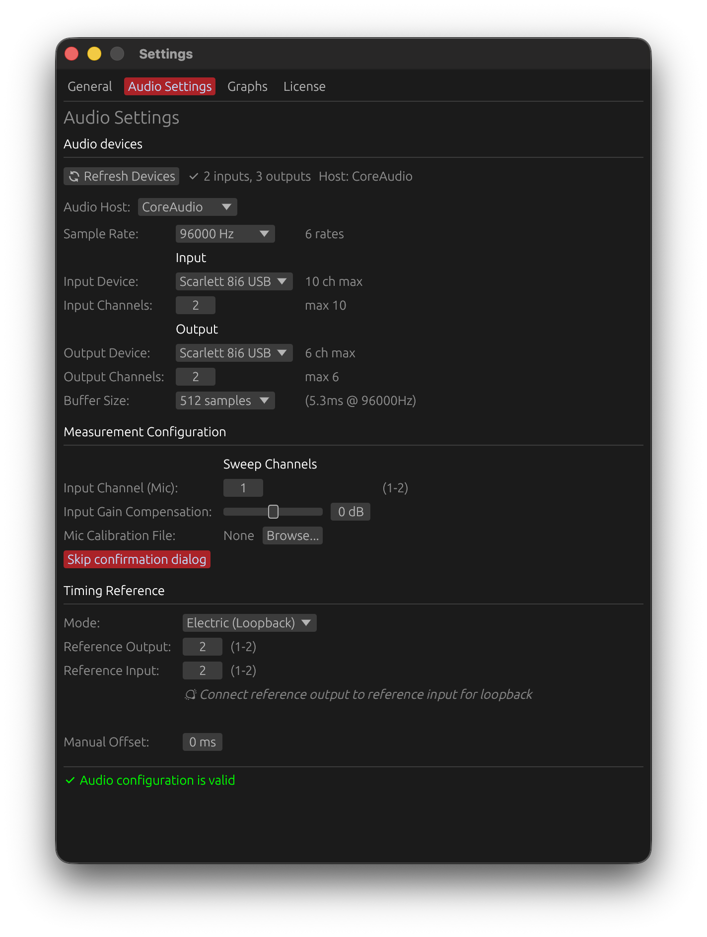

Device Selection
Input Device
The input device captures audio from microphones or measurement equipment:
- Click the dropdown to see available input devices
- Select your measurement microphone or audio interface input
- Verify the device shows the correct channel count
- Ensure the device isn’t in use by another application
Output Device
The output device plays back sweep signals or test tones:
- Select the audio interface connected to your loudspeaker system
- Verify the device supports the desired sample rate
- Check that the device has sufficient channels for your application
Refreshing Devices
If your audio device doesn’t appear:
- Click “Refresh Devices” to rescan available hardware
- Ensure the device drivers are properly installed
- Check that the device is powered on and connected
- Try restarting the application if the device remains unavailable
Sample Rate Configuration
Choose a sample rate matching your needs:
- 44.1 kHz: CD quality, most common for consumer audio
- 48 kHz: Professional audio standard, video production
- 88.2/96 kHz: High-resolution audio, improved time-domain precision
- 176.4/192 kHz: Ultra-high resolution (use only when necessary for THD analysis)
⚠️ Note: The sample rate must be supported by both your input and output devices. If a rate is unavailable, try a different value.
Sample Format Detection
LinFIR automatically detects and selects the best compatible audio sample format between your input and output devices:
- 16-bit integer (I16): Standard for most consumer audio devices
- 24-bit integer (I24): Professional audio interfaces (e.g., Dante Virtual Soundcard, RME, MOTU)
- 32-bit float (F32): High-end interfaces, ASIO and Core Audio devices
- 32-bit integer (I32): Some professional hardware
The format is automatically negotiated during measurement setup - no manual configuration required. If LinFIR cannot find a compatible format, try:
- Using ASIO drivers (Windows) for better professional interface support
- Updating your audio interface drivers
- Checking device sample rate compatibility
Buffer Size
Buffer latency is compensated internally and has no effect on measurement accuracy. The only criterion for choosing a buffer size is avoiding underruns (audio dropouts caused by the buffer emptying before it can be refilled).
- Smaller buffers (128-256 samples): More demanding on the CPU — increase the risk of dropouts on slower systems
- Recommended (512-1024 samples): Reliable on most systems
- Larger buffers (2048+ samples): Maximum stability, useful if dropouts persist
If you experience audio dropouts during measurements, increase the buffer size. Otherwise, any value works.
Input Gain Compensation
Software-based gain adjustment applied to the input signal:
- Range: -32 dB to +32 dB
- Purpose: Compensate for fixed or unavailable hardware gain controls
- Use case: Particularly useful for USB microphones like UMIK-1 on Mac OS
Why Use Input Gain Compensation?
Some measurement microphones have fixed gain or no hardware gain control, particularly on certain platforms:
- Mac OS USB microphones: Mac OS enforces very low fixed gain for USB microphones
- UMIK-1 example: No hardware control available in Mac OS system settings
- Solution: Use positive gain compensation (+18 to +24 dB) to achieve optimal recording levels
Important Notes
- Input gain compensation does not improve signal-to-noise ratio
- It’s a convenience feature for level matching, not a replacement for proper gain staging
- Optimal SNR still requires appropriate acoustic levels and microphone positioning
- Use hardware gain controls when available for best results
Default Sweep Parameters
Configure default settings for the built-in sweep measurement system. These apply to new measurement captures and can be accessed in the Audio Settings tab under Measurement Configuration.
Sweep Duration
Range: 1.0 to 10 seconds
Default: 5 seconds
Default length of exponential sine sweep (ESS) for impulse response measurements.
- Shorter (1.0-2s): Faster measurements, lower frequency resolution
- Longer (5-10s): Better low-frequency resolution, improved signal-to-noise ratio, better harmonic distortion measurement
Benefits of longer sweeps:
- Improved signal-to-noise ratio for harmonic distortion analysis
- Better frequency resolution at low frequencies
- More reliable detection and separation of weak harmonics
⚠️ Important: Longer sweeps deliver more energy to the driver at low frequencies (exponential sweeps spend more time in the bass region). For drivers with limited excursion capability, this may require raising the start frequency or reducing the sweep level to avoid over-excursion.
Recommendation: 5-7 seconds for full-range measurements, 2-3 seconds for quick driver checks.
Sweep Level
Range: -40 to 0 dBFS
Default: -6 dBFS
Default output level for sweep signals.
Adjust this to match your amplifier’s input sensitivity and desired acoustic level. Lower values provide headroom for systems with high gain.
Start Frequency
Range: 1 to 5000 Hz
Default: 1 Hz
Default cutoff frequency for the 4th-order Butterworth high-pass filter applied to the sweep signal for driver protection.
Filter Characteristics:
- Attenuation at Start Frequency: -3 dB (Butterworth characteristic)
- Roll-off below cutoff: -24 dB/octave (deterministic, 4th order)
Frequency Guidelines:
- 1 Hz: Lowest configurable frequency, captures near-DC response
- 20 Hz: Typical for full-range loudspeaker measurements
- 60-70 Hz: Example for 80 Hz passband (accounts for -3 dB at cutoff)
- >1000 Hz: Tweeter protection (above resonance frequency)
⚠️ Critical: Position Start Frequency slightly below your desired passband start to compensate for the -3 dB attenuation at cutoff, but always above driver safety limits. Setting too low can cause mechanical or thermal damage.
See Start Frequency: Driver Protection for detailed guidance on driver-specific settings.
Note on high frequency: The high frequency is automatically calculated to optimize harmonic distortion measurement quality (1/48 octave before Nyquist), typically ~23.5 kHz at 48 kHz sample rate, ~47 kHz at 96 kHz.
Using Default Values
These default values are applied when:
- Opening a new measurement window for the first time
- Clicking the Reset Start Freq button in the measurement window
- Creating a new driver without saved sweep parameters
Changing these defaults affects only future measurements - existing measurements retain their configured parameters.
Platform-Specific Considerations
Mac OS
- Timing stability: Excellent (< 0.01ms typical jitter)
- Timing reference: Optional when the same device is used as input and output but recommended for best accuracy
- Multi-interface: Highly reliable even with different input/output devices
- USB microphones: May require input gain compensation due to OS-enforced low gain with usb devices
Windows
- Timing stability: Variable (1-150ms jitter due to scheduler instability)
- Timing reference: Strongly Recommended (Electric or Acoustic mode) for absolute timing accuracy
- Timing inconsistency: IR arrival time may vary without timing reference
- ASIO drivers: Provide improved stability compared to WASAPI
- Measurement averaging: Works with or without timing reference (continuous capture method)
A timing reference on Windows improves absolute timing consistency when comparing measurements across drivers.
Configuration Checklist
Before starting measurements, verify:
- Input device selected and recognized
- Output device selected and functional
- Sample rate matches project settings
- Buffer size set to 256 or 512 samples
- Input gain compensation configured (if needed)
- Microphone calibration loaded (if available)
- Timing reference configured (see Reference Timing below)
- Devices not in use by other applications
Reference Timing for Sweep Measurements
Accurate timing is critical for consistent impulse response measurements, especially when capturing multiple measurements for averaging or multi-position analysis. LinFIR provides three timing reference modes to accommodate different hardware configurations and platform requirements.
Why Timing Reference Matters
Audio playback and recording systems introduce latency from:
- Digital-to-analog conversion (output)
- Analog-to-digital conversion (input)
- Buffer processing delays
- Operating system scheduler variability
Without a stable timing reference, each measurement may have slightly different latency, making:
- Driver alignment unreliable
- Directivity analysis inaccurate (time-of-flight variations)
Timing Reference Modes
None
No timing reference - relies solely on system scheduler timestamps.
How it works:
- Uses operating system audio clock
- Timestamps based on buffer callback timing
- No additional hardware or connections required
When to use:
- Mac OS systems (low scheduler jitter, typically < 0.01 ms)
- Single-shot measurements without averaging
- Simple setups where high precision isn’t critical
Limitations:
- Windows: Not recommended due to significant scheduler jitter (1-150 ms)
- IR arrival time may vary between captures
Mac OS: Reliable and accurate for most applications when using the same device as input and output. Windows: Avoid for professional work - use Electric or Acoustic mode instead.
Electric (Loopback)
Uses a physical cable connection between output and input to provide a stable timing reference.
How it works:
- Connect line output to line input with a cable
- Loopback signal captures exact OS and electrical latency
- Combined electrical and conversion latency measured
- Provides sample-accurate timing reference
Setup:
- Connect output channel to spare input channel with audio cable
- Select “Electric” timing reference mode in Audio Settings
- Ensure loopback channel is not the measurement input channel
- Run sweep - loopback captures timing automatically
Advantages:
- Most accurate timing reference
- Platform-independent reliability
- Compensates for interface-specific latency
- Eliminates scheduler jitter completely
When to use:
- Windows systems (strongly recommended)
- Designing crossovers
- Professional applications requiring highest accuracy
- Different input/output devices (aggregate devices)
Limitations:
- Requires spare input channel for loopback
- Requires physical cable connection
- May not be available on simple USB audio interfaces
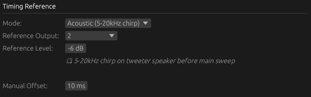
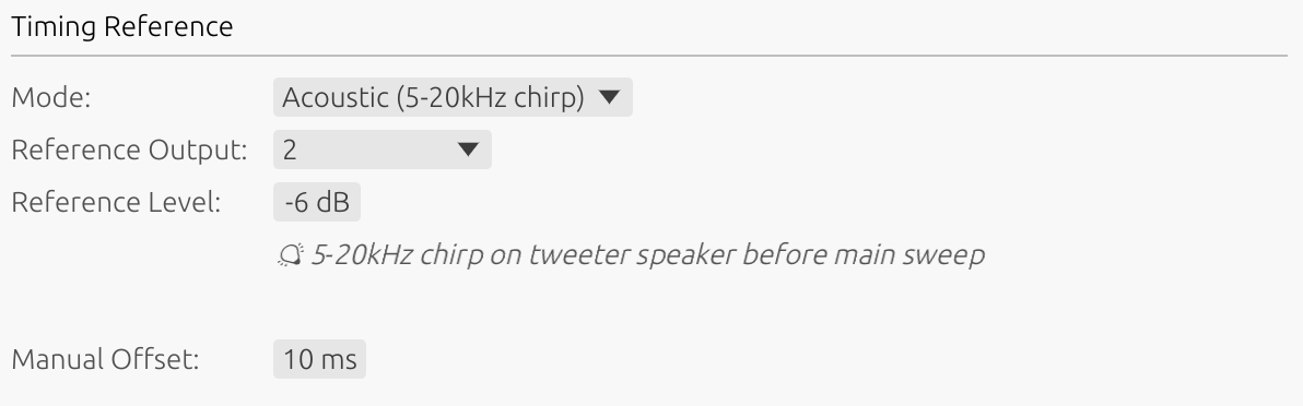
Acoustic
Uses another driver (reference driver) as a timing microphone.
How it works:
- Reference driver captures sweep output acoustically
- Provides stable timing reference based on acoustic arrival
- Measures relative timing between reference and measured driver
- Does not capture true absolute acoustic + electrical travel time
Setup:
- Select a reference driver (must reproduce high frequencies > 5 kHz)
- Position reference driver microphone to capture sweep clearly
- Select “Acoustic” timing reference mode in Audio Settings
- Reference driver captures timing on each sweep
Advantages:
- No loopback cable required
- Works when electrical loopback unavailable
- Good alternative for Windows users without spare input channels
- Suitable for multi-driver directivity measurements
When to use:
- Loopback hardware not available
- Windows systems (recommended alternative to None)
Limitations:
- Only measures relative timing (not absolute acoustic delay)
- Reference driver must reproduce high frequencies cleanly
- Acoustic path must be clear and consistent
- Less accurate than Electric mode
Important: Reference driver should be full-range or at least capable of reproducing 5-10 kHz cleanly for reliable timing detection.
Manual Offset (Preferences)
Adjustable time offset to shift the impulse response position.
- Range: ±4000 ms
- Applies to: All timing reference modes (None, Electric, Acoustic)
- Purpose: Shift the IR forward or backward in time
Use in all modes (convenient)
The offset can be used in any timing mode to position the IR at a convenient location in the window — for example, to center it or add pre-delay before a gate. This is optional and has no impact on accuracy.
⚠️ Caution: A positive offset shifts the IR earlier in the window. If the offset is too large (positive), the impulse peak may move before t=0 and be clipped. Keep the offset small enough to leave sufficient pre-delay in front of the impulse.
Use in Acoustic mode (required in certain cases)
In Acoustic mode, the timing reference is based on the acoustic arrival at the reference driver. If the reference driver is at a similar or shorter distance from the microphone than the measured driver, the IR of the measured driver will appear at time zero or even before it — making it impossible to capture the full impulse response.
In this case, a positive offset must be applied to shift the IR forward and restore the expected relative delay.
Example — reference closer than measured driver:
- Reference driver is 150 cm from the microphone
- Measured driver is 200 cm from the microphone
- Acoustic delay difference ≈ 1.5 ms (50 cm / 343 m/s)
- Apply a positive offset just above ~1.5 ms — large enough to place the impulse response after t=0 with a safety margin
- Use the same offset, mic distance, and reference driver for all measurements in the project — since the offset is constant, the relative acoustic delay between drivers is preserved, enabling accurate temporal alignment when designing crossovers
Fine-tuning:
- Run test measurement
- Check impulse response time alignment
- Adjust offset in small increments
- Re-measure to verify alignment
Platform Requirements
Windows
- Averaging: Works with or without timing reference (continuous capture eliminates jitter issues)
- Scheduler jitter: Significant (1-150 ms variable latency) for initial timing only
- Recommendation: Timing reference still recommended for absolute timing accuracy across sessions
- Single measurements: Work with “None” mode but may have timing variation
Without timing reference on Windows:
- Each measurement has unpredictable latency
- Directivity analysis compromised
- Time and phase alignment between drivers will lead to wrong results
Mac OS
- Scheduler jitter: Minimal (< 0.01 ms typical)
- Recommendation: Timing reference optional but still beneficial for best accuracy
- Multi-interface: More stable than Windows even without reference
Choosing the Right Mode
| Situation | Recommended Mode |
|---|---|
| Windows + single shots | Acoustic or Electric (None acceptable) |
| Mac OS + single shots | None acceptable, Electric for best accuracy |
| Different input/output devices | Electric strongly recommended |
| Directivity measurements | Electric or Acoustic |
| Crossover design | Electric or Acoustic |
| No spare input channel | Acoustic (Windows) or None (Mac OS) |
Configuration Workflow
-
Assess requirements:
- Single measurement or averaging?
- Mac OS or Windows?
- Spare input channel available?
-
Select mode:
- Windows averaging → Electric or Acoustic
- Mac OS → None acceptable, Electric for best results
- No loopback → Acoustic (if reference driver available)
-
Setup hardware (if Electric):
- Connect output to spare input channel
- Verify loopback signal path
-
Setup reference driver (if Acoustic):
- Select driver with good high-frequency response
- Position reference microphone to capture sweep clearly
-
Configure in Audio Settings:
- Select timing reference mode
- Adjust timing offset if needed (Acoustic mode)
-
Test:
- Run test measurement
- Verify timing consistency
- Adjust offset if required
Timing Reference Troubleshooting
Inconsistent Measurements
Symptom: Each measurement has different arrival time
Cause: No timing reference active
Solution: Enable Electric or Acoustic mode
Reference Signal Not Detected
Symptom: Error message about missing reference
Cause: Loopback not connected or reference driver not capturing sweep
Solution:
- Electric: Verify cable connection and input channel selection
- Acoustic: Ensure reference driver can reproduce sweep frequencies
Timing Offset Not Working
Symptom: Impulse still misaligned after offset adjustment
Cause: Incorrect offset direction or magnitude
Solution:
- Try opposite sign (positive ↔ negative)
- Increase offset magnitude
- Verify reference driver is capturing sweep correctly
Best Practices
- Windows users: Always use Electric or Acoustic mode for professional work
- Loopback preferred: Most accurate, eliminates all timing variables
- Acoustic alternative: Good fallback when loopback unavailable
- Test before session: Verify timing consistency with test measurements
- Document settings: Record timing mode and offset in project notes
- Consistent hardware: Use same interface for all measurements in a session
Troubleshooting
Device Not Listed
- Click “Refresh Devices” to rescan
- Ensure device drivers are installed
- Check that device isn’t in use by another application
- Try different sample rates or buffer sizes
- Restart LinFIR
Configuration Invalid
- Selected devices may have been disconnected
- Sample rate may not be supported by device
- Channel count may exceed device capabilities
- Try selecting default devices and refreshing
Audio Dropouts
- Increase buffer size
- Close other applications using audio
- Check for system resource constraints
- Update audio interface drivers
No Sound During Sweep
- Verify output device is selected and powered on
- Check system audio settings
- Ensure exclusive mode isn’t blocking access (Windows)
- Try different buffer sizes
- Verify output channel selection in IR Management window