Driver Processing
Each driver in LinFIR can be individually processed with a comprehensive signal chain combining FIR crossovers, FIR correction filters, IIR equalization, polarity inversion, and time/gain adjustments.
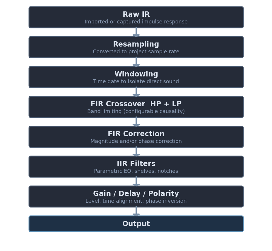
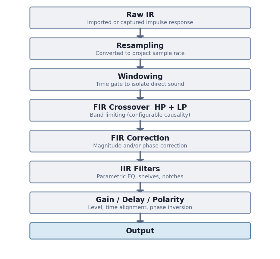
The processing chain for each driver follows this order:
Driver Management
Adding and Removing Drivers
Add Driver:
- Maximum: 10 drivers per project
- Click ➕ Add Driver button in the Drivers toolbar
- New driver initialized with default settings
Remove Driver:
- Click 🗑 button in the driver’s bottom action bar
- Only visible when more than one driver is present
- Hidden in Hypex mode (driver count is locked by the selected model)
Copy / Paste Driver Parameters:


- Click 📋 to copy all parameters of a driver to the clipboard
- IRs and driver name are not copied — only filter and DSP settings
- Copied parameters include: FIR/IIR filters, gain, time delay, polarity, tap lengths, windowing, correction settings, mic calibration, and sweep parameters
- Click 📥 to paste the clipboard parameters onto another driver
- The target driver’s IRs and name are preserved
- The 📥 button is grayed out when no parameters have been copied yet
- Useful for duplicating crossover or EQ settings across multiple drivers without redoing each one manually
Driver Organization:
- Drivers are organized in collapsible sections in the left toolbar
- Each section shows the driver name (or “Driver 1”, “Driver 2”, etc. if unnamed)
- Driver names are automatically set when importing impulse responses
Driver Controls
Enable/Disable and Solo
Enable Toggle:
- Button to enable/disable individual drivers
- Disabled drivers are excluded from calculations and the summed response
- Useful for A/B testing or isolating specific drivers
Solo Button:
- Instantly disables all other drivers and enables only the selected driver
- Quick way to review individual drivers in isolation
All Button:
- Re-enables all drivers simultaneously
- Convenient after using Solo mode
Driver Interface Overview
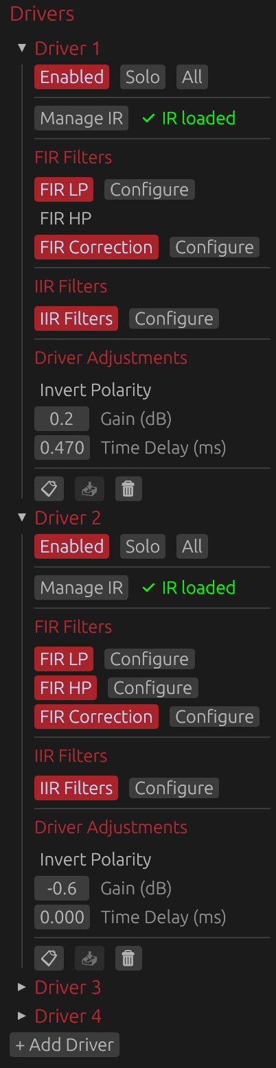
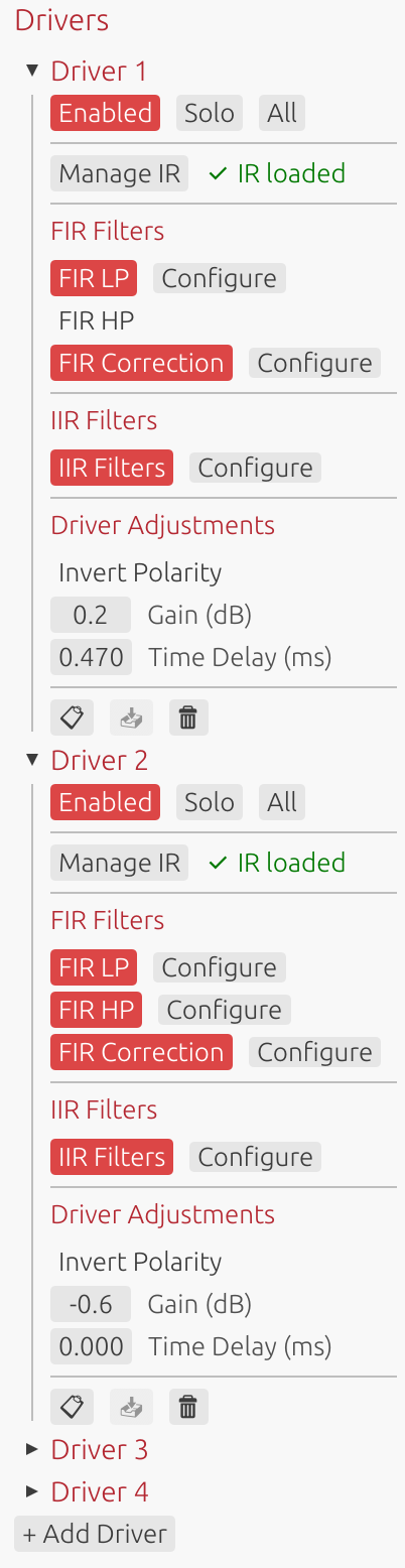
Each driver’s interface provides access to all processing and configuration options, organized into three main sections:
- Manage IR: Import/capture impulse responses and configure windowing
- FIR Filters: Low-pass, high-pass, correction filters, and FIR offset delay (if enabled in global settings)
- IIR Filters: Parametric EQ and filter design
- Driver Adjustments: Polarity inversion, gain, and time delay adjustments
The following sections detail each of these components.
Impulse Response Management
Loading Impulse Responses
Click Manage IR to open the impulse response management window for:
- Importing pre-recorded impulse responses
- Capturing new measurements via audio interface
- Configuring IR windowing parameters
- Managing off-axis measurements for directivity analysis
See IR Management for detailed documentation.
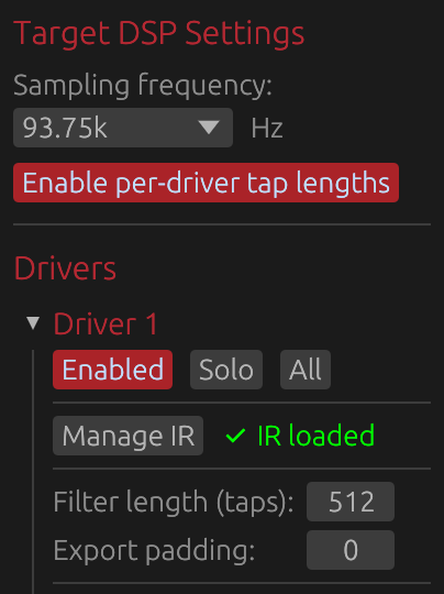
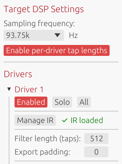
IR Status Indicator:
- Gray “No IR loaded”: Driver has no impulse response
- Green “✅ IR loaded”: Valid impulse response loaded
⚠️ Note: A loaded impulse response is required for filter design and correction. Without an IR, only theoretical filter responses can be displayed.
Target DSP Settings
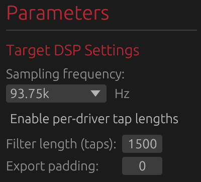
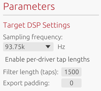
The Target DSP Settings section configures fundamental parameters that determine filter design constraints and export characteristics. These settings directly impact frequency resolution, latency, and compatibility with your target DSP platform.
⚠️ Note: You can change these settings at any time to match different DSP characteristics, but doing so will affect the precision, effectiveness, delays, and slopes of any FIR filters you have already set.
Sample Rate
Options: 44.1 kHz, 48 kHz, 88.2 kHz, 93.75 kHz, 96 kHz, 176.4 kHz, 192 kHz
Current project: Fixed at project creation
The sample rate is set when creating a new project and cannot be changed afterward. It determines:
- Nyquist frequency: Maximum representable frequency (sample rate / 2)
- Filter frequency resolution: Higher rates provide finer resolution
- Latency: For a given tap count, higher sample rates have lower latency in milliseconds
- DSP compatibility: Must match your target DSP platform’s operating sample rate
Common choices:
- 44.1 kHz: Compact DSP platforms with limited processing power
- 48 kHz: Professional audio standard, most DSP platforms
- 88.2 kHz: High-resolution audio (2× CD rate, relatively uncommon for DSP)
- 93.75 kHz: Hypex DSP platforms (FA123, FA253, FA502, etc.)
- 96 kHz: High-resolution audio, some professional DSP platforms
- 176.4/192 kHz: Ultra-high resolution - only when DSP platform specifically requires it
Enable per-driver tap lengths
Default: Disabled (shared tap length applies to all drivers)
When disabled (default):
- Single Filter length (taps) control in Target DSP Settings applies to all drivers
- Single Export padding control in Target DSP Settings applies to all drivers
- Simpler configuration for uniform systems
- All drivers use the same FIR filter length
When enabled:
- Filter length (taps) and Export padding controls move from Target DSP Settings to individual driver sections
- Each driver gets its own controls in its collapsible section
- Allows optimization: fewer taps for tweeters, more for woofers/subwoofers
- Useful for minimizing DSP load while maintaining quality where needed
Example use case: Use 2048 taps for subwoofer (needs low-frequency resolution), 512 taps for tweeter (high frequencies need less resolution).
⚠️ Note: Linear phase FIR filters and phase-correction FIR filters introduce noticeable delays that depend on the number of taps. Different tap lengths between drivers will likely introduce time misalignments, which you can correct using the Time Delay parameter in the Driver Adjustements section.
Filter Length (Taps)
Range: 32 to 65536 taps
Default: 512 taps
Location:
- Shared mode (per-driver tap lengths disabled): In Target DSP Settings section - applies to all drivers
- Per-driver mode (per-driver tap lengths enabled): In each driver’s collapsible section
Controls the length of all FIR filters for this driver (crossover and correction filters).
Frequency Resolution:
- Resolution (Hz) = Sample Rate / Tap Count
- Example at 48 kHz: 512 taps = 93.75 Hz resolution, 4096 taps = 11.72 Hz resolution
- Lower frequencies need more taps for precise control
Latency (Linear-Phase):
- Latency = (Taps / 2) / Sample Rate
- Example at 48 kHz: 512 taps = 5.33 ms, 4096 taps = 42.67 ms
- Can be reduced using Causality control at the cost of phase linearity
Practical guidelines:
- 256-512 taps: Tweeters, minimal latency applications
- 512-2048 taps: Most crossover and correction applications
- 2048-4096 taps: Typical maximum for full-range loudspeaker designs
- 4096-8192 taps: Subwoofer correction, room correction
- 8192-16384 taps: Specialized low-frequency correction below 20 Hz
- >16384 taps: Rarely needed (extreme cases, research purposes)
Trade-offs:
- ✅ More taps = better frequency resolution, steeper filter slopes, more precise correction
- ❌ More taps = higher latency (for linear-phase), increased DSP load, larger export files
Export Padding
Range: 0 to 65536 taps
Default: 0
Location:
- Shared mode (per-driver tap lengths disabled): In Target DSP Settings section - applies to all drivers
- Per-driver mode (per-driver tap lengths enabled): In each driver’s collapsible section
Adds zero-padding only to exported files, without affecting internal processing or design.
Purpose:
- Some DSP platforms require specific filter lengths (e.g., powers of 2: 512, 1024, 2048, 4096)
- Padding allows meeting DSP requirements without changing internal design
- Does not affect latency, delay, or any graph displays
How it works:
- Internal design: Uses configured tap count
- Export: Appends zeros to reach (Taps + Padding) length
- Frequency response remains identical (zero-padding doesn’t alter frequency content)
Example scenario:
- Design with 3000 taps, DSP requires power-of-2 → Set padding to 1096 → Exports 4096 taps
When not needed: If your DSP accepts arbitrary filter lengths, leave padding at 0.
FIR Crossover Filters
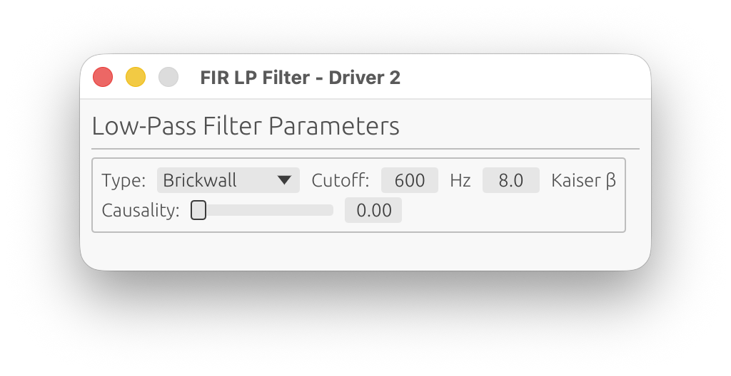
FIR Low-Pass Filter
Enable: Toggle FIR LP button
Configure: Click Configure button (only available when enabled)
Applies a linear-phase low-pass filter to limit the driver’s high-frequency response.
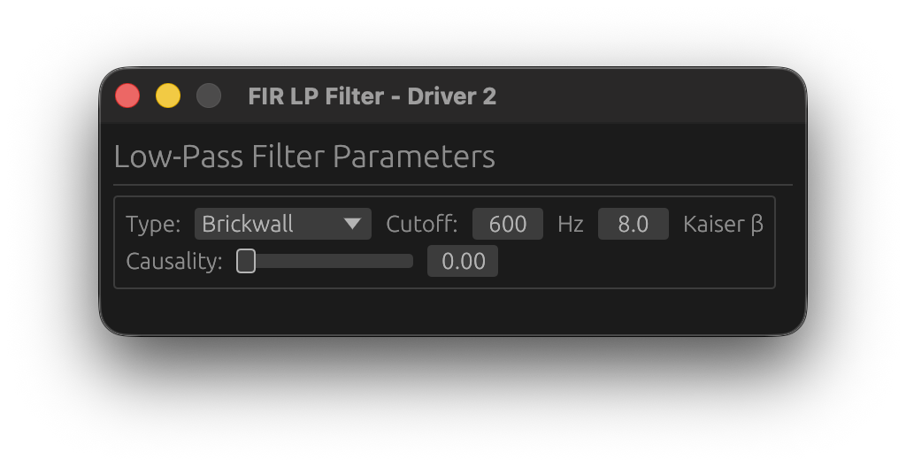
Parameters:
Filter Type
Choose the crossover filter design:
-
Brickwall: Ideal brickwall (Sinc) filter using Kaiser window
- Sharpest possible slope
- Controlled transition width via Kaiser β parameter
-
Linkwitz-Riley: Linkwitz-Riley aligned response
- -6 dB at crossover frequency (sums to 0 dB when paired with matching HP)
- Constant power summing when combined with complementary HP filter
- Order: 2, 4, 6, 8, or 10 (even orders only)
-
Butterworth: Classic analog-style Butterworth response
- Maximally flat magnitude in passband
- Order: 1 to 10
-
Bessel: Bessel/Thomson response
- Originally optimized for linear phase response and minimal group delay variation
- Gentler roll-off than Butterworth
- Order: 1 to 10
Cutoff Frequency
Range: 1 Hz to Nyquist frequency
Step: 1 Hz
The -6 dB point for brickwall filters, or the characteristic frequency for Butterworth/Linkwitz-Riley filters.
Typical values:
- Woofer-Midrange: 300-800 Hz
- Midrange-Tweeter: 2-4 kHz
Kaiser β
Range: 0.0 to 50.0
Default: 8.0
Controls the Kaiser window applied to the FIR filter impulse response. This parameter adjusts the trade-off between transition width and stopband ripple:
For Brickwall filters:
- Lower values (3-5): Narrower transition BUT higher stopband ripple (higher sidelobe levels)
- Moderate values (6-10): Balanced transition width and stopband attenuation
- Higher values (12-20): Wider transition BUT lower stopband ripple (better attenuation)
For Butterworth, Linkwitz-Riley and Bessel filters:
- Controls FIR windowing to suppress ringing and ripple in the stopband
- Lower values (3-5): Sharper response BUT higher ripple/ringing in stopband
- Moderate values (6-10): Good balance between sharpness and ripple suppression
- Higher values (12-20): Gentler response BUT maximum ripple suppression
Common choices:
- β = 5: Narrow transition with noticeable ripple (not necesarrily audible as the complementary driver will mask it)
- β = 8-9: Standard crossover design, good compromise
- β = 12-15: Wide transition with excellent stopband attenuation
Order (Butterworth/Linkwitz-Riley/Bessel only)
Butterworth/Bessel Range: 1, 2, 3, 4, 5, 6, 7, 8, 9, 10
Linkwitz-Riley Range: 2, 4, 6, 8, 10 (even only)
Higher order = steeper slope (more dB/octave attenuation).
- 2nd order: 12 dB/octave (gentle slope)
- 4th order: 24 dB/octave (most common for LR designs)
- 6th order: 36 dB/octave
- 8th order: 48 dB/octave (steep slope)
Causality
Range: 0.0 (linear-phase) to 1.0 (minimum-phase)
Default: 0.0 (linear-phase)
Interpolates between linear-phase and minimum-phase behavior for the FIR crossover filter.
Purpose: Limits the delay introduced by the FIR filter while maintaining steeper slopes than IIR filters, at the cost of phase distortion.
Linear-Phase (0.0):
- Symmetric pre- and post-ringing
- Constant group delay across all frequencies
- No phase distortion
- Highest latency (taps/2 samples)
- Best for high-fidelity applications
Minimum-Phase (1.0):
- No pre-ringing (all energy is causal)
- Variable group delay
- Phase follows magnitude via Hilbert transform
- Minimal latency
- Best for low-latency applications
Intermediate values:
- Blend between linear and minimum phase
- Reduced pre-ringing compared to linear-phase
- Some phase distortion compared to linear-phase
- Lower latency than full linear-phase
Typical values:
- 0.0: High-fidelity systems, studio monitors, reference designs
- 0.5: Balanced compromise
- 1.0: Low-latency systems, live sound, PA applications
Trade-off: Increasing causality reduces latency but introduces phase distortion. For multi-driver systems, matching causality settings across all drivers maintains phase coherence.
FIR High-Pass Filter
Enable: Toggle FIR HP checkbox
Configure: Click Configure button (only available when enabled)
Applies a linear-phase high-pass filter to limit the driver’s low-frequency response.
Parameters: Identical to FIR Low-Pass (Type, Cutoff, Kaiser β, Order, Causality)
Linkwitz-Riley and Brickwall Crossover Design: When using complementary LR filters (e.g., woofer LP at 500 Hz + midrange HP at 500 Hz, both 4th order), the combined magnitude response is flat at the crossover point.
FIR Correction Filter
Enable: Toggle FIR Corr button
Configure: Click Configure button (only available when enabled)
Applies frequency-domain magnitude and/or phase correction using the loaded impulse response.
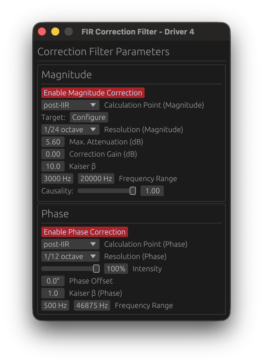
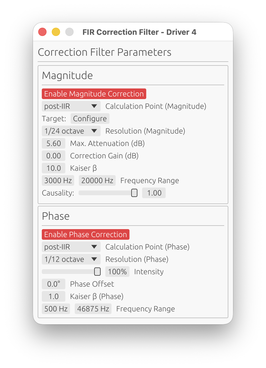
The correction filter window has two main sections: Magnitude and Phase.
Magnitude Correction
Enable Magnitude Correction
Toggle to enable/disable magnitude response correction independently from phase.
Calculation Point
Choose where correction is calculated in the processing chain:
-
pre-IIR: Correction computed from raw IR before IIR filters
- Use when IIR filters are for fine-tuning only
- Simpler, doesn’t account for IIR response
-
post-IIR: Correction computed after IIR filter application
- Accounts for IIR filter effects in the correction calculation
- Use when IIR filters significantly alter the response
- More accurate for complex filter chains
Target Curve
Click Configure to open the target curve configuration window.
Purpose: Define the desired magnitude response for this driver.
See Target Curves for detailed configuration.
Frequency Range
Start Frequency:
- Range: 1 Hz to Nyquist
- Default: 20 Hz
- Lower limit for magnitude correction
End Frequency:
- Range: 1 Hz to Nyquist
- Default: Nyquist
- Upper limit for magnitude correction
Purpose: Restrict correction to a specific frequency range, avoiding correction where measurements are unreliable or correction is undesirable.
Important: Magnitude correction applies a smooth taper (transition zone) at the frequency range boundaries to prevent discontinuities:
- Taper width: Quarter-octave (1/4 octave) above and below the correction range
- Taper function: Raised cosine (smooth fade-in/fade-out)
- Below Start Frequency: Correction weight fades from 0% at
Start / 2^(1/4)to 100% atStart - Above End Frequency: Correction weight fades from 100% at
Endto 0% atEnd × 2^(1/4) - Example: For Start = 200 Hz, the taper begins at 168 Hz. For End = 10 kHz, the taper extends to 11.9 kHz
- Purpose: Ensures smooth transitions without abrupt magnitude steps or phase artifacts
Critical Understanding: Correction Source Signal
The magnitude correction filter is computed from the driver’s impulse response without FIR low-pass or high-pass filters applied (those are applied later in the signal chain). The correction sees:
- ✅ IIR filters (if “post-IIR” calculation mode is enabled)
- ❌ FIR LP/HP crossovers (not applied yet)
Practical Implications:
1. With IIR Crossovers (post-IIR mode):
- The correction attempts to flatten the IIR crossover rolloff
- ⚠️ This removes your crossover slope, which is usually undesirable
- Solution: Limit the frequency range to roughly your driver’s final passband
- Example: For a tweeter with IIR HP at 2 kHz, set correction range to 2.5 kHz - 20 kHz
2. With pre-IIR mode or FIR crossovers:
- The correction sees the driver’s raw natural rolloff
- Risk: Amplifying rolloff increases noise and distortion outside the intended band
- Sometimes helpful: Can improve summation in the crossover transition region
- Solution: Set frequency range to where summation matters, don’t extend further
- Example: For a midrange crossing at 500 Hz and 3 kHz, limit to 400 Hz - 4 kHz
Best Practice: Configure the frequency range to match your driver’s intended operating band considering your crossover strategy, not just where the measurement looks good.
Resolution
Options: 1/48 oct, 1/24 oct, 1/12 oct, 1/6 oct, 1/3 oct
Default: 1/12 octave
Fractional-octave smoothing applied to the measured response before computing the correction filter. This determines the resolution of features that will be corrected.
Purpose: Avoid correcting measurement artifacts (reflections, diffraction ripples, noise) that are not inherent to the speaker’s response.
- 1/48 oct to 1/24 oct: Minimal smoothing - risks correcting artifacts and creating excessive filter complexity
- 1/12 oct: Recommended balance - corrects real speaker behavior while ignoring fine ripples
- 1/6 to 1/3 oct: Heavy smoothing - corrects only broad trends
Key principle: The correction filter resolution should match the reliability of your measurement, not its raw resolution. Narrow features (<1/12 oct) are often artifacts, not real acoustic properties worth correcting.
Recommendation: Use 1/12 octave for typical speaker correction, 1/6 octave for room measurements or when measurement quality is uncertain.
Max. Attenuation (dB)
Range: 0 to 30 dB
Default: 10 dB
Maximum attenuation applied by the magnitude correction filter.
How it works: The correction filter works by “cutting from the top” - it attenuates peaks in the measured response to bring them down toward the target curve. This parameter limits how much attenuation is applied.
Purpose:
- Prevents excessive notching of narrow peaks (which may be measurement artifacts)
- Keeps the correction filter smooth and stable
- Avoids creating deep notches that could be audible as resonances
Typical values:
- 5-8 dB: Conservative correction for well-behaved drivers
- 10 dB: Standard value for most applications
- 12-15 dB: More aggressive correction (check impulse response for artifacts)
- >15 dB: Rarely needed, may indicate measurement issues
Important: The correction filter primarily attenuates rather than boosts. Use Correction Gain (below) to compensate for the overall level reduction.
Correction Gain (dB)
Range: -20 to +20 dB
Default: 4 dB
Gain applied within the correction frequency range to compensate for the attenuation introduced by the magnitude correction filter.
Purpose:
- Restores overall level after attenuation-based correction
- Allows fine-tuning the driver’s output level
- Maintains consistent loudness across the corrected frequency band
Typical values:
- 0-4 dB: Minimal compensation (gentle correction)
- 4-6 dB: Standard compensation for moderate correction
- 6-10 dB: High compensation (use with caution)
⚠️ Warning: Excessive correction gain can cause clipping in the internal DSP signal chain or damage your drivers. Keep gain reasonable (< 6 dB recommended) to maintain headroom. If LinFIR’s clipping detection is enabled (see Settings), you’ll receive warnings about potential clipping.
Kaiser β (Magnitude)
Range: 0.0 to 50.0
Default: 8.0
Kaiser windowing parameter for the magnitude correction FIR filter.
Effect:
- Lower values (3-5): Sharper correction BUT may amplify ripple from crossover filters (LP/HP) if active
- Moderate values (6-10): Good balance between precision and ripple suppression
- Higher values (12-20): Smoother correction, reduced ripple amplification, but less precise
When to adjust:
- If you see excessive ripple in the stopband after applying correction with active crossover filters, increase Kaiser β
- If correction seems too gentle or imprecise, decrease Kaiser β
Recommendation: Start with default 8.0, increase to 12-15 if ripple is problematic with crossover filters active.
Causality (Magnitude)
Range: 0.0 (linear-phase) to 1.0 (minimum-phase)
Default: 1.0 (minimum-phase)
Controls the phase characteristic of the magnitude correction filter.
- 0.0 (Linear-phase): Symmetric pre- and post-ringing, constant group delay
- 1.0 (Minimum-phase): No pre-ringing, all energy is causal, variable group delay
Typical choice: 1.0 (minimum-phase) to avoid pre-ringing artifacts.
Why minimum-phase is preferred: Most acoustic and electronic systems are minimum-phase (magnitude and phase are coupled via Kramers-Kronig relations). Correcting magnitude with a minimum-phase filter automatically corrects the associated phase deviation, providing physically accurate correction. Use 0.0 (linear-phase) only if you specifically need constant group delay with a non-flat target curve and can tolerate pre-ringing.
Phase Correction
Enable Phase Correction
Toggle to enable/disable phase response correction independently from magnitude.
🚫 Non-anechoic measurements: phase correction is strongly discouraged
Phase correction requires clean, accurate phase data. In-room measurements contain reflections, room modes, and position-dependent artifacts that pollute the phase response. Applying phase correction to such data produces unpredictable — and often worse — results.
Only use phase correction with anechoic or near-anechoic measurements (e.g., measurements gated to remove reflections, or made in an anechoic chamber). For in-room measurements, restrict correction to magnitude only.
⚠️ Critical Limitation: Phase Correction vs. Low Latency
You cannot have both near-zero latency FIR filters AND active phase correction. This is a fundamental limitation, not a software bug.
Why this incompatibility exists:
Even if you configure your FIR crossover filters (HP/LP) and FIR magnitude correction with causality = 1.0 (minimum-phase, low latency), which positions the FIR impulse peak near t=0 (left-aligned), enabling phase correction will shift the combined FIR impulse peak to the center (around ntaps/2), introducing significant latency.
The reason is fundamental:
- Phase correction = temporal correction: Phase distortion is fundamentally a time-domain problem (different frequencies arriving at different times)
- To correct temporal defects, you need time: The filter needs temporal “space” before and after the main impulse to reposition frequency components correctly
- This requires centering the impulse: Phase correction filters must have headroom both before (pre-ringing) and after (post-ringing) the main signal to perform time-domain manipulations
- Result: The combined FIR impulse peak moves from t≈0 (low latency) to t≈ntaps/2 (high latency)
Practical impact:
- Without phase correction: Causality=1.0 filters → impulse peak at t≈0 → latency ≈ 0 samples
- With phase correction enabled: Impulse peak moves towards t≈ntaps/2 → latency ≈ ntaps/2 samples (e.g., 2048 samples at 48kHz = 42.7ms)
Recommended approach:
- For low-latency applications (live sound, PA, monitoring): Use causality = 1.0 on crossover/magnitude filters, disable phase correction, accept phase as-is
- For high-fidelity applications (studio monitors, reference systems): Use causality = 0.0 on crossover, 1.0 on magnitude filters, enable phase correction if needed, accept the latency
- For hybrid approach: Use moderate causality (0.3-0.7) for reduced latency with some phase correction capability (but still expect significant latency when phase correction is active)
Calculation Point
Same as magnitude: pre-IIR or post-IIR calculation mode.
pre-IIR: Phase correction computed from raw IR before IIR filters
post-IIR: Phase correction computed after IIR filter application
Resolution (Phase)
Options: 1/48 oct, 1/24 oct, 1/12 oct, 1/6 oct, 1/3 oct
Default: 1/12 octave
Fractional-octave smoothing applied to the measured phase response before computing the correction filter.
Recommendation: Use heavier smoothing (1/6 to 1/3 octave) for phase correction to avoid chasing measurement noise and room reflections.
Intensity
Range: 0% to 100%
Default: 100%
Controls the amplitude/strength of the phase correction.
Purpose:
- Allows partial phase correction for smoother transitions
- Reduces phase correction aggressiveness if full correction creates artifacts
- Useful for blending between corrected and uncorrected phase
Typical values:
- 100%: Full phase correction (default)
- 50-80%: Partial correction for gentler results
- 0%: No phase correction (disabled)
Phase Offset
Range: -180° to +180°
Default: 0°
Phase offset applied to the filter’s phase response.
Purpose: Controls the symmetry of the impulse response by adjusting the phase offset. This allows fine-tuning the balance between pre-ringing and post-ringing in the time-domain response.
How it works:
- 0°: Default even symmetric behavior
- Positive/Negative offset: Shifts impulse response characteristics towards odd symmetry
Use case: Advanced parameter for optimizing impulse response symmetry in multi-driver systems.
Recommendation: Leave at 0° unless you have specific symmetry requirements and understand impulse response trade-offs.
Kaiser β (Phase)
Range: 0.0 to 50.0
Default: 1.0
Kaiser windowing parameter for the phase correction FIR filter.
Effect:
- Lower values (1-5): Less aggressive windowing — the correction filter’s oscillations (pre- and post-ringing) are preserved more fully, allowing accurate phase correction at the cost of slower roll-off at the filter edges
- Moderate values (6-10): Balanced windowing — trade-off between accuracy and artifact suppression
- Higher values (12-20): Aggressive windowing — strongly attenuates the filter’s pre- and post-ringing; if correction energy is clipped by the window, this introduces magnitude deviations
When to adjust:
- If the guard warning appears (the auto-guard has already narrowed the Start/End Frequencies as far as it can): decrease Kaiser β — see Phase Correction Magnitude Artifacts below
- If phase correction seems imprecise or creates excessive ringing, increase Kaiser β
Recommendation: Start with default 1.0. If the guard warning still appears after the guard’s automatic frequency adjustments, try reducing β toward 0.
Guard Tolerance
Range: 0.1 dB to 15 dB
Default: 0.5 dB
Maximum magnitude deviation the auto-correction guard will tolerate before narrowing the correction band. Above this threshold, the guard automatically raises the Start Frequency in 1/3-octave steps (and eventually lowers the End Frequency) until the phase FIR stays within tolerance — see Phase Correction Magnitude Artifacts.
- Tighter (0.1–0.5 dB): Stricter — the guard narrows the band more aggressively. Recommended for high-fidelity correction.
- Looser (1–5 dB): More permissive — allows a wider correction band at the cost of some magnitude coloration.
Frequency Range (Phase)
Start Frequency:
- Range: 0 Hz to Nyquist
- Default: 0 Hz
End Frequency:
- Range: 0 Hz to Nyquist
- Default: Nyquist
Limits the frequency range over which phase correction is applied.
Use cases:
- Focus correction on the driver’s primary operating band (e.g., 200 Hz – 10 kHz for a midrange)
- Exclude deep bass where phase rotations would require very long filters
- Anchor the correction band manually when the auto-guard’s automatic adjustments are not desirable
Note: The auto-correction guard already raises the Start Frequency automatically when artifacts are detected. Only set it manually to intentionally anchor the correction start frequency.
Phase Correction Magnitude Artifacts
A phase correction FIR filter is designed to be magnitude-neutral — it should modify only the phase of the signal, leaving energy at each frequency unchanged. However, in practice, magnitude deviations can appear after applying phase correction. LinFIR includes an auto-correction guard that detects and corrects these automatically.
Why artifacts occur
Phase correction works in the time domain: correcting a phase rotation at a given frequency means shifting energy from one moment in time to another. This produces an impulse response with oscillations extending both before and after the central peak (pre- and post-ringing). The lower the frequency being corrected, the longer these oscillations extend, because a given phase rotation translates to a longer time shift at lower frequencies.
Two mechanisms can cause the filter to deviate from magnitude-neutral behavior:
1. Insufficient tap count
If the number of taps allocated to the phase correction filter is too small, the filter’s oscillations extend beyond the available window — they are truncated at the boundaries. Truncating a non-zero portion of the filter’s impulse response distorts its frequency response, introducing magnitude ripples proportional to the energy that was cut off.
This is analogous to abruptly cutting off a signal in the time domain and observing Gibbs-like ringing in the frequency domain.
2. Overly aggressive Kaiser windowing (high β)
The Kaiser window tapers the filter’s impulse response toward zero at both ends. A high β value applies a strong taper. This strongly attenuates the pre- and post-ringing of the phase correction filter — even if those oscillations were within the allocated tap window.
Attenuating oscillations that carry real correction energy distorts the filter’s frequency response, producing magnitude deviations — typically attenuations that grow stronger as the window becomes more aggressive.
Auto-correction guard
LinFIR includes an auto-correction guard that runs automatically every time the phase correction FIR is computed — it is always active. The guard:
- Computes the phase correction FIR with the current Start and End Frequencies
- Measures the maximum magnitude deviation within the active passband
- If the deviation exceeds Guard Tolerance, raises the Start Frequency by 1/3-octave steps and retries
- Once the Start Frequency reaches its ceiling (~15 kHz), lowers the End Frequency instead (down to ~18 kHz)
- Repeats up to 100 iterations until the deviation stays within the Guard Tolerance threshold
The guard silently narrows the effective correction band until the phase FIR becomes magnitude-neutral. Under normal circumstances no warning appears — the guard resolves artifacts transparently.
When the guard warning appears
If the guard exhausts all 100 iterations without reducing the deviation below Guard Tolerance, it gives up and — if Warn when phase FIR guard fails is enabled in Settings — shows a warning. At this point the guard has already narrowed the frequency band as far as it can, yet the FIR still deviates. Manual intervention may help:
-
Reduce Kaiser β (most effective)
High β aggressively clips filter oscillations, directly causing magnitude deviations. Since the guard only adjusts frequency boundaries and not Kaiser β, reducing β is the first thing to try.
→ Reduce from the current value toward 1.0 or lower. -
Increase the tap count
More taps give the filter more temporal “space” to express its oscillations without truncation. This is especially important for corrections at low frequencies.
→ Double the tap count and check if the warning disappears. -
Raise Guard Tolerance
If the residual deviation is small enough to be acceptable, relax the threshold.
→ Set Guard Tolerance to 1–2 dB and assess whether the audible impact is acceptable. -
Reduce the phase correction intensity
Lower intensity reduces filter complexity and correction energy.
→ Try setting Intensity to 70–80%.
⚠️ Before adjusting filter parameters, inspect the phase and group delay plots first.
A guard warning that resists all of the above is often a symptom of a measurement quality problem, not a filter configuration problem. Accumulated phase rotations caused by reflections or resonances in the impulse response force the phase correction filter to work on chaotic, non-monotonic data — producing an unstable, artifact-prone FIR regardless of the parameters chosen.
In Loudspeaker Design mode: Measurements must be taken with the least possible room influence. Use time windowing (Start/Stop Time in IR Management → Time Windowing) to gate out reflections before applying phase correction. Use the Auto Set Window function as a starting point, then review the phase and group delay plots — they should be smooth and monotonic in the driver’s passband. Irregular phase jumps or group delay peaks indicate reflections or resonances that windowing should remove.
In Room Calibration mode: Impulse windowing is intentionally not available — this mode is designed to capture the full speaker-plus-room response. Applying a temporal window would yield an anechoic-like response, which would be misleading: corrections derived from it would be wrong for the actual listening environment, because your ears do not apply a time window. To reduce spatial variability and limit the influence of isolated reflections on the measured phase, capture at least 5 or 6 measurements at different listening positions and rely on spatial averaging — see Room Calibration Mode.
Even so, phase correction is strongly discouraged in room calibration mode. The room dominates the phase response — modal resonances, flutter echo, and comb filtering from reflections produce chaotic phase behavior that varies dramatically across the listening area. Even with spatial averaging, a phase correction filter derived from in-room data is likely to be spatially unstable: it may improve the phase at the measurement positions while worsening it elsewhere, and may introduce audible coloration or artifacts. No DSP technique can substitute for acoustic treatment when it comes to correcting room-induced phase problems.
FIR Correction Best Practices
-
Start conservative:
- Begin with 1/6 or 1/3 octave smoothing
- Limit maximum gain to 6-12 dB
-
Narrow frequency range:
- Only correct the driver’s intended operating band
- Don’t correct below woofer resonance or above tweeter range
- Avoid correcting crossover stopband region
-
Magnitude before phase:
- Get magnitude response flat first
- Then add phase correction if needed
- Phase correction is most effective with flat magnitude
-
Check impulse response:
- Excessive pre-ringing indicates too aggressive correction
- Increase smoothing or reduce max gain if pre-ringing is severe
-
Combine with IIR:
- Use FIR correction for broad trends
- Use IIR filters for narrow notches and fine adjustments
IIR Filtering
Enable: Toggle IIR Filters checkbox
Configure: Click Configure button (only available when enabled)
Apply cascaded biquad IIR filters for parametric equalization and precise frequency shaping.
IIR Filter Tabs
The IIR window has two tabs:
Manual Tab
Design custom IIR filter chains with up to 50 filters.
Add Filter: Click ➕ Add Filter button
Remove Filter: Click ❌ button next to filter
Available Filter Types:
- Peak/Notch: Parametric EQ (boost/cut at specific frequency)
- Low Shelf: Boost/cut below shelf frequency
- High Shelf: Boost/cut above shelf frequency
- Low-Pass: Frequency-selective attenuation (high frequencies)
- High-Pass: Frequency-selective attenuation (low frequencies)
- All-Pass: Phase adjustment without magnitude change
Filter Parameters:
Frequency:
- Center frequency for Peak/Notch
- Cutoff frequency for LP/HP/Shelves
- Corner frequency for All-Pass
Gain (dB):
- Boost (+) or cut (-) amount
- Only for Peak/Notch and Shelving filters
- Range: -40 to +40 dB
Q Factor:
- Filter bandwidth/sharpness
- Higher Q = narrower bandwidth
- Typical range: 0.5 to 20
- Low Q (0.5-2): Wide, gentle curves
- Medium Q (2-5): Standard parametric EQ
- High Q (10-20): Narrow notches for resonance control
Order (LP/HP only):
- Filter slope steepness
- Range: 1 to 10 (depending on filter type)
- Each order adds 6 dB/octave slope
Pass Type:
- Low-Pass, High-Pass: Frequency-selective filtering
- Peak/Notch: Standard parametric EQ
Locked Filters (🔒):
Individual filters can be locked to preserve them during operations:
- Lock toggle: Click the 🔓/🔒 icon next to any filter to lock/unlock it
- Protected from Clear: Locked filters are not deleted when clicking “Clear Filters”
Use Cases:
- Lock protective filters (high-pass, low-pass) to preserve them when clearing other filters
- Preserve manually tuned filters when experimenting with different EQ approaches
- Protect critical filters (driver protection, subsonic filters) from accidental deletion
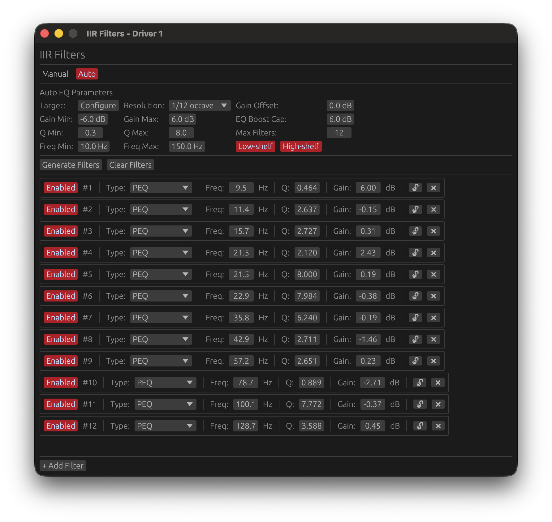
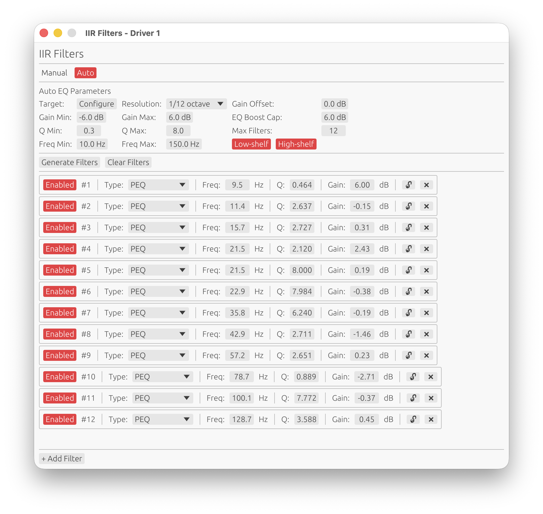
Auto Tab
Automatically generated equalization with manual control.
Adding Filters:
- Click ➕ Add Filter to manually add filters in Auto EQ tab
- Add protective filters (high-pass, low-pass, notches) before running Auto EQ
- Lock them with 🔒 icon to preserve during Auto EQ generation
Manual Editing:
- All filters in Auto EQ tab are editable (frequency, gain, Q)
- Adjust auto-generated filters directly without cloning
- Lock important filters to prevent removal during regeneration
Generate Auto EQ:
- Click Generate to automatically create corrective filters
- Auto EQ respects locked filters (integrates HP/LP into target curve)
- Unlocked filters are replaced with new auto-generated corrections
Copy to Manual:
- Click Clone from Auto EQ to copy the entire filter set to Manual tab
- Useful for preserving a working Auto EQ configuration while experimenting in Manual
Auto-generate (requires license)
- Enable the Auto-generate toggle to automatically re-generate filters whenever any parameter in the Auto EQ tab changes — frequency range, gain limits, resolution, shelves, etc.
- When first activated, a generation is immediately triggered with the current parameters
- Only parameter changes within the Auto EQ tab trigger regeneration; changes in the Manual tab or other driver settings have no effect
- Changing the target curve does not trigger auto-generation. To apply a new target curve, click Generate Filters manually or change any parameter in the Auto EQ tab after selecting the new curve
🔑 License required: The Auto-generate toggle requires a valid LinFIR license. Without a license, it is disabled and greyed out.
Target curve overlay
When the IIR filter window is open and in the foreground with the Auto EQ tab selected, the configured target curve is displayed as a blue overlay directly on the frequency response graph. The curve is level-matched to the driver’s smoothed response over the configured frequency range, and truncated to [Freq Min, Freq Max]. It disappears automatically when the IIR window is sent to the background.
Auto EQ Parameters
When you click Generate in the Auto EQ tab, the optimizer uses the following parameters to create corrective filters:
Gain Offset:
- Range: -20 to +20 dB
- Default: 0 dB
- Purpose: Adjusts the overall target level before EQ optimization
- Use case: Compensate for overall system level shifts without changing filter gains
Gain Min / Gain Max:
- Range: -20 to +20 dB
- Default: -6 to +6 dB
- Purpose: Limits the boost/cut range for each individual filter
- Use case: Prevent excessive corrections that could cause clipping or sound unnatural
EQ Boost Cap:
- Range: 0 to +20 dB
- Default: 6 dB
- Purpose: Soft-clips the correction target to prevent filter stacking at the same frequency
- Use case: Set lower values (e.g., 4 dB) for more conservative corrections
Q Min / Q Max:
- Range: 0.1 to 20.0
- Default: 0.3 to 8.0
- Purpose: Controls the bandwidth/sharpness of generated filters
- Use case: Lower Q = wider corrections, higher Q = narrow notches for resonances
Max Filters:
- Range: 1 to 30
- Default: 12
- Purpose: Maximum number of filters to generate (including shelves if enabled)
- Use case: More filters = more precise correction, but more phase impact
Freq Min / Freq Max:
- Range: 10 to 22,000 Hz
- Default: 20 to 20,000 Hz
- Purpose: Defines the frequency range for filter placement and correction
- Important: Auto EQ applies a quarter-octave taper (1/4 octave) above and below these frequency limits to ensure smooth transitions without discontinuities in the correction
- How the taper works:
- Below
Freq Min: Correction weight gradually reduces from 100% atFreq Minto 0% atFreq Min / 2^(1/4)(quarter-octave below) - Above
Freq Max: Correction weight gradually reduces from 100% atFreq Maxto 0% atFreq Max * 2^(1/4)(quarter-octave above) - Outside taper zones: No correction applied (weight = 0%)
- Below
- Use case: Focus correction on the driver’s operating band, exclude problematic regions (e.g., below resonance, room modes, or above useful bandwidth)
Low Shelf / High Shelf:
- Toggle: Enable/disable shelf filters
- Purpose: Allow AutoEQ to include shelving filters for broad tonal adjustments
- Use case: Enable for better overall tonal balance, disable for peaking-only corrections
Resolution:
- Options: 1/48, 1/24, 1/12, 1/6, 1/3 octave
- Default: 1/12 octave
- Purpose: Smoothing applied to the current response before optimization
- Use case: Higher smoothing (1/3 oct) = broader corrections, lower smoothing (1/48 oct) = more detailed corrections
IIR Filter Applications
Parametric EQ (Peak/Notch):
- Boost/cut specific frequencies
- Correct narrow resonances or notches
- Fine-tune response after FIR correction
Shelving Filters:
- Broad treble/bass adjustments
- Tilt EQ for overall tonal balance
- Baffle step compensation
- Psychoacoustic tuning
Notch Filters:
- Suppress driver resonances
Low-Pass/High-Pass:
- Additional crossover filtering (complements FIR)
- Subsonic/ultrasonic filtering
All-Pass:
- Phase correction without affecting magnitude
- Time alignment adjustments
- Advanced multi-driver phase matching
IIR Best Practices
-
Use sparingly:
- Fewer filters = cleaner phase response
- Each biquad adds phase rotation
- Prefer FIR correction for broad magnitude shaping
-
Narrow adjustments:
- IIR excels at narrow peaks/notches
- Use Q > 5 for resonances
- Use Q < 2 for broad tonal adjustments
-
Check phase impact:
- View phase plot when adding IIR filters
- High-Q filters create significant phase rotation
- Consider if phase impact is acceptable
-
Combine with FIR:
- FIR correction for broad trends (1/3 to 1/6 oct smoothing)
- IIR filters for narrow resonances and fine details
- Best of both worlds
Driver Adjustments
Polarity Inversion
Toggle: Polarity button
Inverts the driver’s signal (180° phase shift across all frequencies).
Use cases:
- Correct out-of-phase drivers
- Optimize multi-driver summation (especially for dipole/bipole designs)
- Fix inverted wiring
- Align asymmetric crossovers
How to check:
- Observe step response: positive step should have initial positive rise
- Check summed magnitude: in-phase drivers sum coherently (+6 dB), out-of-phase drivers cancel
Gain Adjustment
Range: -40 to +40 dB
Step: 0.1 dB
Default: 0 dB
Adjusts the driver’s output level.
Use cases:
- Compensate for driver sensitivity differences
- Set target SPL for each driver
- Balance multi-driver systems
- Fine-tune summed response
Time Delay
Range: 0.0 to 100.0 ms
Step: equivalent to 1 sample (depends on target sampling frequency)
Default: 0.0 ms
Adds pure time delay to the driver’s output.
Use cases:
- Align drivers physically offset from each other
- Compensate for acoustic center differences
- Time-align multi-way systems for coherent summation
- Correct for DSP processing delays
Calculation:
- Distance (m) to delay (ms): delay = distance / 0.343 m/ms
- Example: 10 cm offset = 0.291 ms delay
Delay Step Size:
- Automatically adjusted based on sample rate
- Higher sample rates allow finer delay precision
- Use fine adjustments for critical time alignment
FIR Compensation Delay
Range: 0.0 to 100.0 ms
Step: equivalent to 1 sample (depends on target sampling frequency)
Default: 0.0 ms
Additional delay applied only to the FIR filter chain, not the entire signal.
Purpose:
- Manual control over FIR filter impulse positioning
- Fine-tune FIR filter alignment when Auto Causal Alignment is disabled
- Shift FIR maximum to optimal crop window position
Use case: When combining multiple causal FIR filters, the impulse maximum may shift. FIR Compensation Delay allows manually repositioning the combined FIR response to avoid truncation. It is not the primary timing alignment tool—use the Time Delay feature for that.
Recommendation: Use Auto Causal Alignment unless you need precise manual control.
Processing Chain Summary
The complete driver processing chain:
-
Raw Impulse Response
- Loaded via IR Management window
- Windowed with configurable start/stop times
-
FIR Crossover Filters
- High-pass filter (if enabled)
- Low-pass filter (if enabled)
- Applied in time domain
-
FIR Correction Filter
- Magnitude correction (if enabled)
- Phase correction (if enabled)
- Applied in time domain
-
Combined FIR Filters
- All FIR filters convolved into single impulse response
- Cropped to configured tap length
- Causality interpolation applied
-
IIR Filtering
- Cascaded biquad sections
- Applied in time domain (as SOS transfer function)
-
Driver Adjustments
- Polarity inversion (if enabled)
- Gain adjustment
- Time delay
-
Final Output
- Processed driver response
- Summed with other drivers for system response
💡 Visualising filter impact: When a filter window (LP, HP, correction FIR, or IIR) is open for a driver, LinFIR can overlay a dashed pre-filter curve on the frequency, phase, and group delay graphs. This shows the driver response at step 1 (after windowing, before any filtering), letting you see exactly how much correction a filter is applying without switching views. Enable this in Settings → Graphs → Response Overlays → Show raw response when filter windows are open (requires a valid license).
Workflow Recommendations
Starting a New Driver
- Load impulse response via Manage IR
- Configure windowing to isolate direct sound
- Set filter length (512-4096 taps for most designs)
- Add FIR crossover (LP/HP) if needed
- Apply FIR correction (start conservative: 1/6 oct smoothing, 12 dB max gain)
- Check summed response, adjust gain/delay for coherent summation
- Add IIR filters for fine-tuning (narrow resonances, shelves)
- Optimize causality if latency is critical
- Export filters for DSP deployment
Multi-Way Design
- Load all driver IRs (woofer, midrange, tweeter)
- Set crossover frequencies based on driver capabilities
- Apply complementary crossovers (e.g., LR4 at matching frequencies)
- Check phase alignment and IR (step) summation in phase and IR (step) plots
- Adjust time delays to align acoustic centers
- Check summed magnitude for flat on-axis response
- Fine-tune with IIR for final voicing
- Verify step response for correct polarity and alignment
Keyboard Shortcuts
- Cmd+W / Ctrl+W: Close configuration windows (LP, HP, Correction, IIR)
- F: Switch to Filters display mode
- D: Switch to Drivers display mode
- U: Toggle wrapped/unwrapped phase
- C: Toggle time of flight rotation removal
See Keyboard Shortcuts for complete reference.
Related Documentation
- IR Management: Detailed impulse response loading and windowing
- System Processing: Global FIR correction and system-level processing
- Export: Exporting filters for DSP platforms
- Settings: Application-wide settings and defaults