Project Modes
LinFIR offers three specialized operating modes, each designed for specific audio engineering workflows. The mode is selected during project creation and determines the available features and interface elements throughout the project’s lifetime.
Note on Hypex FusionAmp mode: The Hypex FusionAmp mode is a derivative of Loudspeaker Design mode. Everything documented for Loudspeaker Design — driver processing, crossover design, FIR/IIR filtering, measurement import, directivity analysis — applies equally to Hypex FusionAmp projects. The mode adds hardware-specific UI constraints (locked sample rate, fixed channel count, FIR tap limits, IIR biquad limit) that prevent invalid configurations and eliminate the need to manually track hardware limits during the design process.
Loudspeaker Design Mode
Purpose
This mode is optimized for designing and analyzing multi-way loudspeaker systems. It provides comprehensive tools for crossover design, driver integration, and directivity analysis.
Key Features
- Multi-driver support: Design systems with multiple drivers (subwoofers, woofers, midranges, tweeters)
- Crossover: FIR and IIR crossover filters with various types
- Driver correction: Individual magnitude and phase correction for each driver
- Directivity tools: Analyze off-axis response and polar patterns (license required)
- Complete export: Export individual driver filters, global filters, and HFD configurations

Typical Workflow
- Create a new Loudspeaker Design project
- Import or measure impulse responses for each driver
- Design crossover filters (low-pass, high-pass)
- Apply frequency response corrections
- Analyze summed system response
- Export filters for DSP implementation
When to Use
- Designing passive loudspeaker conversions to active DSP
- Optimizing existing multi-way systems
- Analyzing driver interactions and phase relationships
- Creating custom crossover
- Performing anechoic or quasi-anechoic measurements
Room Calibration Mode
Purpose
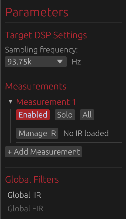
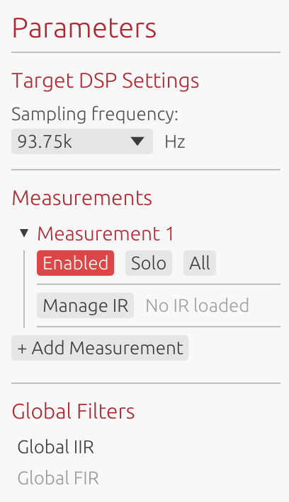
Dedicated to in-room acoustic measurements and correction filter generation. This mode focuses on capturing multiple measurement positions, aligning them temporally, and creating averaged correction filters.
Key Features
- Multiple measurement positions: Capture IRs at different listening locations
- Automatic temporal alignment: GCC-PHAT algorithm aligns measurements
- Spatial averaging: Creates averaged response across measurement positions
- Global correction only: Simplified interface focused on room correction
- Streamlined export: Export only global correction filters
Typical Workflow
- Create a new Room Calibration project
- Configure sweep output channel
- Capture measurements at 3-5 different listening positions
- Measurements are automatically aligned using GCC-PHAT
- Design global correction filters (FIR and/or IIR)
- Export correction filters for room EQ implementation
UI Adaptations
When in Room Calibration mode, the interface adapts to focus on relevant features:
- Disabled: Directivity analysis tools (not applicable to room measurements)
- Simplified: Filter graphs show only global filters
- Restricted: Export options limited to global correction filters
- Hidden: Individual driver processing controls
Export Restrictions
Room Calibration projects export only:
- Global FIR correction filter (if enabled)
- Global IIR filters (Manual or Auto-EQ)
The following exports are disabled:
- HFD config export
- Detailed reports (TXT/PDF)
- Individual driver filters
This ensures clean, focused output for room correction workflows.
When to Use
- Correcting in-room frequency response
- Creating stereo-linked or mono room correction
- Working with existing loudspeaker systems
- Integrating with convolution engines
Hypex FusionAmp Mode
⚠️ License required: Creating Hypex FusionAmp projects requires a valid LinFIR license. See License for activation details.
Purpose
Hypex FusionAmp mode is a derivative of Loudspeaker Design mode tailored specifically for Hypex FusionAmp series amplifiers (FA122, FA123, FA251, FA252, FA253, FA501, FA502, FA503). All Loudspeaker Design features are available — driver processing, crossover design, FIR/IIR filtering, measurement import, directivity analysis — but several parameters are locked to match the DSP capabilities of the target hardware.
The goal is to eliminate manual bookkeeping: instead of counting biquads, tracking tap budgets, or checking compatibility after the fact, the UI enforces hardware limits in real time so the resulting configuration is always valid and ready to export.
Available Models
LinFIR supports all FusionAmp models:
- FA122: 2-channel amplifier (2 × 125W @ 4Ω)
- FA123: 3-channel amplifier (2 × 125W + 100W @ 4Ω)
- FA251: 1-channel amplifier (1 × 250W @ 4Ω)
- FA252: 2-channel amplifier (2 × 250W @ 4Ω)
- FA253: 2-channel amplifier (2 × 250W + 100W @ 4Ω)
- FA501: 1-channel amplifier (1 × 500W @ 4Ω)
- FA502: 2-channel amplifier (2 × 500W @ 4Ω)
- FA503: 3-channel amplifier (2 × 500W + 100W @ 4Ω)
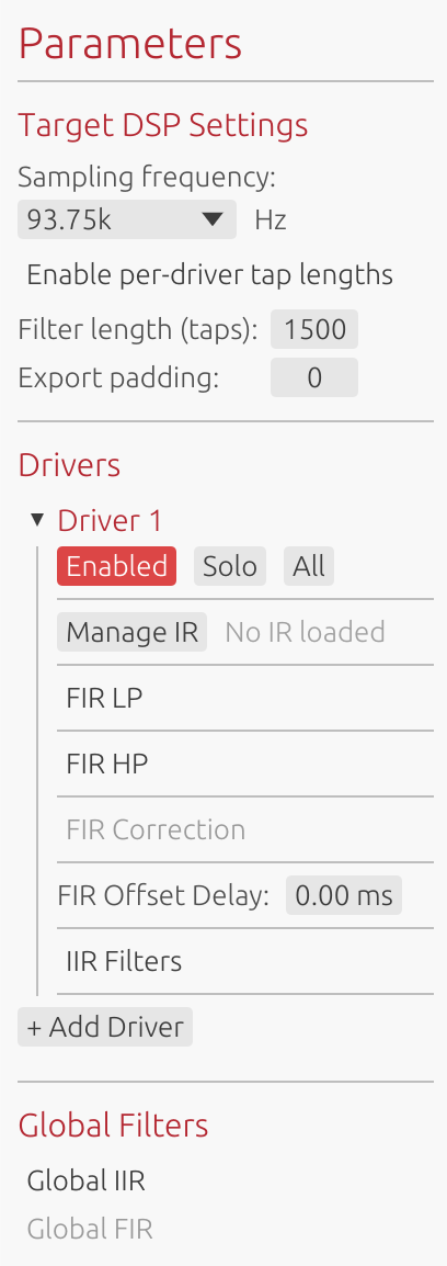
Hardware Constraints
When in Hypex FusionAmp mode, several parameters are locked to match hardware specifications:
- Sample Rate: Fixed at 93.75 kHz (cannot be changed)
- Channel Count: Fixed by model (1, 2 or 3 channels, cannot add/remove drivers)
- IIR Filters: Maximum 15 biquads per channel
- FIR Filters: Fixed total tap count depends on FIR position (see below)
FIR Processing Modes
FusionAmp mode offers two mutually exclusive FIR processing configurations:
FIR IN (Input FIR)
Global FIR correction applied at the DSP input stage before channel processing.
- Location: Before IIR filters and channel routing
- Total taps: Fixed at 4500 (filter taps + padding)
- Use case: Global room correction, global speaker compensation
- Constraint: FIR Taps + Export padding = 4500 (always)
- UI behavior: Per-driver FIR controls are hidden; adjusting taps automatically adjusts padding to maintain 4500 total
FIR OUT (Output FIR)
FIR correction applied at the output stage, after IIR processing.
- Location: After IIR filters, per-channel or global
- Total taps: Fixed at 1500 per channel (filter taps + padding)
- Use case: Individual driver correction, per-channel equalization
- Constraint: Filter length (taps) + Export padding = 1500 (always, per driver or global)
- UI behavior: Adjusting taps automatically adjusts padding to maintain 1500 total
IIR Filter Constraints
FusionAmp DSP limits each channel to 15 biquads maximum. LinFIR enforces this through:
- Add Filter button: Automatically disabled when at 15 biquads
- Filter type restrictions: Types exceeding the limit are grayed out with tooltips
- Order limitations: Filter order sliders dynamically limited based on remaining capacity
- Auto EQ constraints: “Max Filters” parameter accounts for locked filters’ biquad usage
Note: For details on how biquad counts are calculated for different filter types, see the IIR Filtering section.
Key Features
- Hardware-matched UI: Interface adapts to show only applicable controls
- Automatic validation: Prevents configurations exceeding hardware limits
- Export compatibility: Direct HFD export for FusionAmp amplifiers
- Constraint warnings: Visual indicators when approaching limits
Typical Workflow
- Create new project: File → New Project → Hypex FusionAmp
- Select model (FA122, FA123, FA251, FA252, FA253, FA501, FA502, FA503)
- Choose FIR position (Input or Output)
- Import/measure impulse responses for each channel
- Design IIR filters (monitor biquad counter to stay within 15 biquad limit)
- Configure FIR correction (taps + padding always equals 4500 for IN or 1500 for OUT)
- Export HFD configuration file for amplifier
UI Adaptations
The interface automatically adjusts based on FIR position:
FIR IN mode:
- Global FIR section visible and active
- Per-driver FIR controls hidden
- Taps and padding controls linked to maintain 4500 total
- Adjusting taps automatically recalculates padding, and vice versa
FIR OUT mode with per-driver FIR:
- Per-driver FIR controls visible
- Each driver has linked taps/padding controls maintaining 1500 total
- Global FIR section hidden or disabled
FIR OUT mode without per-driver FIR:
- Taps and padding controls linked to maintain 1500 total
- Per-driver FIR controls hidden
Export Configuration
Hypex FusionAmp projects support:
- HFD export: Native configuration format for FusionAmp amplifiers
- FIR filter export: Individual channel FIR filters
- IIR filter export: Biquad coefficients per channel
When to Use
- Configuring Hypex FusionAmp series amplifiers
- Ensuring DSP configuration fits hardware constraints
- Exporting ready-to-use HFD configuration files
- Working within strict real-time processing limits
Limitations
⚠️ Hardware constraints cannot be bypassed:
- Sample rate is locked at 93.75 kHz
- Channel count is fixed by model (1, 2, or 3 channels)
- FIR total tap count is fixed (4500 for IN, 1500 for OUT) - taps and padding sum must always equal this value
- IIR biquad limit (15 per channel) is strictly enforced
- Cannot use both FIR IN and FIR OUT simultaneously
Mode Selection
Creating a New Project
Project mode is selected via File → New Project:
- Click “New Project”
- Choose between “Loudspeaker Design”, “Room Calibration”, or “Hypex FusionAmp”
- For Hypex FusionAmp: Select model (FA122/FA123/FA251/FA252/FA253/FA501/FA502/FA503) and FIR position (IN/OUT)
- For other modes: Configure initial project settings (sample rate, filter length, etc.)
- Begin working in the selected mode
Mode Permanence
⚠️ Important: Once a project is created, its mode cannot be changed. The mode is permanently associated with the project file.
To work in a different mode:
- Save your current project (if needed)
- Create a new project with the desired mode
- Import measurements or data as required
Choosing the Right Mode
Use Loudspeaker Design Mode when:
- Designing crossovers for multi-driver systems
- Analyzing individual driver characteristics
- Performing directivity analysis
- Working with anechoic or quasi-anechoic data
- Need flexible configuration options
Use Room Calibration Mode when:
- Correcting in-room frequency response
- Creating averaged room correction filters
- Working with existing complete loudspeaker systems
- Focusing on global system correction only
Use Hypex FusionAmp Mode when: (license required)
- Configuring Hypex FusionAmp series amplifiers
- Exporting HFD configuration files
- Need to ensure configurations match hardware limits (93.75 kHz, fixed taps, 15 biquads)
Best Practices
Room Calibration Mode
- Measurement count: Capture 3-5 measurements at different positions
- Position spacing: Keep positions within 30-50 cm of main listening area
- Height consistency: Use consistent microphone height across measurements
- Reference position: First measurement should be at primary listening position
- Correction philosophy: Apply gentle correction, avoid over-equalization
- Deep nulls: Don’t attempt to fill room mode nulls below 300 Hz
- Phase type: Consider minimum-phase FIR for reduced latency
- Acoustic treatment: Combine with room treatment for best results
Loudspeaker Design Mode
- Measurement quality: Use anechoic or quasi-anechoic measurements when possible
- Windowing: Gate reflections using IR time windowing
- Alignment: Align drivers using time delay controls, not FIR compensation delay
- Crossover design: Start with appropriate crossover frequencies and filter slopes
- Phase analysis: Monitor phase relationships between drivers
- Directivity: Capture multiple angles for comprehensive analysis (license required)
Mode Comparison Table
| Feature | Loudspeaker Design | Room Calibration | Hypex FusionAmp (license) |
|---|---|---|---|
| Multi-driver support | ✅ | ❌ (single “system”) | ✅ (1-3 fixed) |
| Individual driver filters | ✅ | ❌ | ✅ |
| Global filters | ✅ | ✅ | ✅ |
| Directivity analysis | ✅ (license) | ❌ | ✅ (license) |
| Multiple measurements | ✅ | ✅ | ✅ |
| Automatic alignment | ❌ | ✅ (GCC-PHAT) | ❌ |
| HFD export | ✅ | ❌ | ✅ |
| IIR filter export | ✅ | ✅ | ✅ (15 biquad limit) |
| Detailed reports | ✅ | ❌ | ✅ |
| THD analysis | ✅ | ❌ | ✅ |
| Sample rate | Configurable | Configurable | 93.75 kHz (locked) |
| Channel count | Configurable | 1 (mono/avg) | 1-3 (model-locked) |
| FIR total taps | Configurable | Configurable | Fixed: 4500 (IN) or 1500 (OUT) |
| IIR biquad limit | None | None | 15 per channel |
Hypex FusionAmp is a superset of Loudspeaker Design: all ✅ features from Loudspeaker Design are available, with the hardware constraints in the last rows added on top.