General Settings
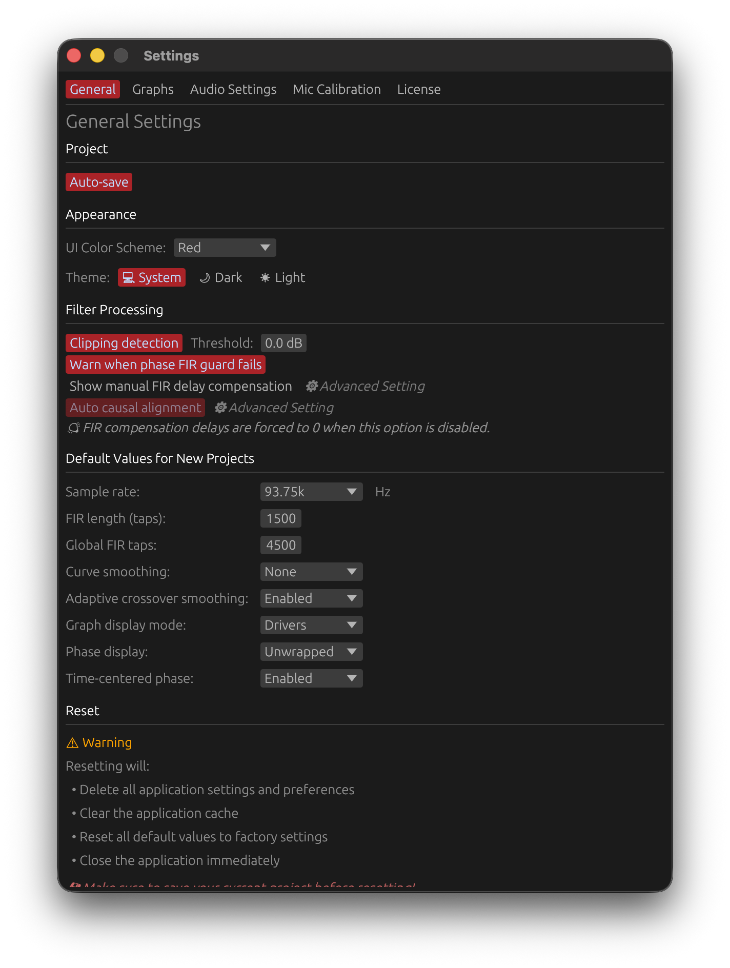
Appearance
Customize the visual appearance of the LinFIR interface.
UI Color Scheme
Choose between two color themes for LinFIR’s interface elements:
- Red (default): Custom red accent colors for headers, titles, and active buttons
- Blue: Standard egui theme with blue accents
What changes:
- Section headers (Parameters, Drivers, Global Filters)
- Graph titles (Frequency Responses, Impulse Responses, etc.)
- Active button colors and selection highlights
- Accent colors throughout the interface
Application: Changes apply immediately without requiring restart.
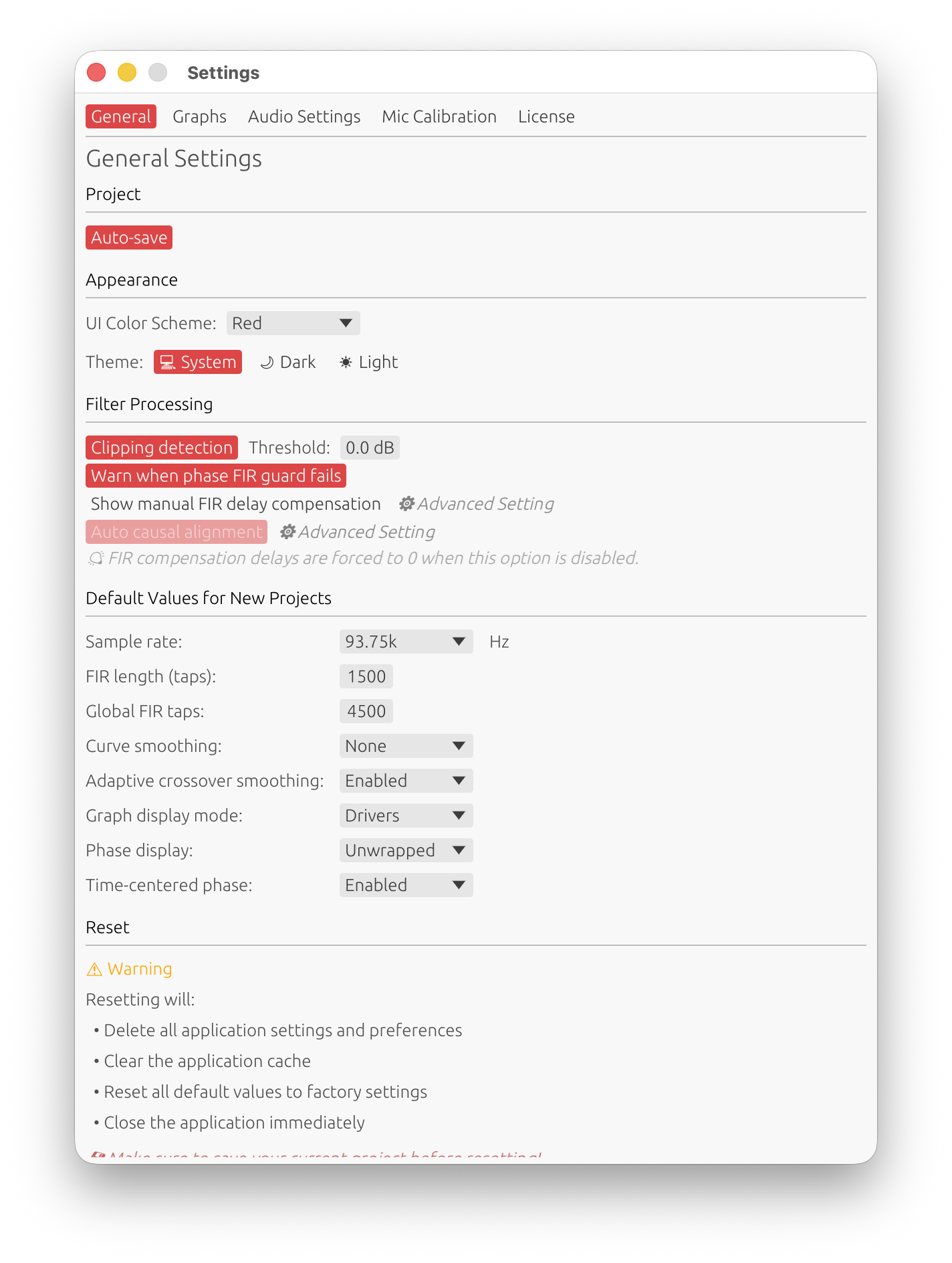
Theme (Light/Dark Mode)
Switch between light mode and dark mode using the system theme preference buttons.
- Light mode: Bright background, dark text
- Dark mode: Dark background, light text
- Follow system: Automatically matches your operating system theme preference
Filter Processing
Settings that affect how filters are computed and validated.
Clipping Detection
Default: Enabled
Threshold: 0 dB (configurable from −5 to +2 dB)
When enabled, LinFIR analyzes filter chains to detect potential clipping and suggests gain adjustments.
How it works:
- Generates a deterministic periodic pink-noise test signal covering 20 Hz to 20 kHz
- Spectral slope: −3 dB/octave (represents typical programme material)
- Band-shaped: 12 dB/oct high-pass at 20 Hz, 24 dB/oct low-pass at 20 kHz
- RMS ≈ −24 dBFS, peak = −6 dBFS (crest factor ≈ 12 dB)
- Applies all active filters to the test signal
- Warns when filter output exceeds the configured threshold
- Suggests gain reduction to bring peak below 0.95 × threshold (leaving a small safety margin)
Threshold setting: The threshold controls the detection sensitivity relative to digital full scale (0 dBFS):
- 0 dB (default): warn when the filter output reaches or exceeds full scale — the standard safety level
- Negative values (−1 to −5 dB): conservative — trigger the warning before reaching full scale, leaving extra headroom.
- Positive values (+1, +2 dB): lenient — only warn when the output is significantly above full scale. Use with caution: values above 0 dB allow actual clipping to go unreported
⚠️ Setting the threshold above 0 dB means clipping can occur without any warning.
Important clarifications:
⚠️ Measurement levels are not tested - Clipping warnings are purely about filter processing, not your imported measurements. The test signal is synthetic and independent of measurement amplitude.
⚠️ Phase processing can cause clipping even with flat magnitude responses - Filters with visually reasonable frequency responses can produce temporal peaks exceeding 0 dBFS. This is especially common with:
- Phase correction filters combined with other filters (without crossovers)
- All-pass filters that only modify phase
- Multiple FIR filters with different causality settings
Why this happens: Phase distortion (or correction) shifts frequency components in time, causing them to align constructively at certain moments. Classic example: a square wave with magnitude 1.0 can exceed 1.0 after phase processing, even though the Fourier magnitude spectrum remains unchanged.
Why disable:
- May improve performance on slower systems
- Removes safety warnings if you’re confident in your gain staging
⚠️ Warning: Disabling removes safety checks. Always test with your actual audio content when clipping detection is disabled.
Warn when phase FIR guard fails
Default: Enabled
When enabled, LinFIR shows a warning toast if the phase correction auto-correction guard exhausted all its attempts without producing a FIR with flat magnitude response.
The auto-correction guard is always active. It automatically raises the minimum/maximum correction frequency (f_min/f_max) in 1/3-octave steps — up to 100 iterations — until the FIR’s magnitude deviation falls within the per-filter tolerance threshold. If every attempt still exceeds the threshold, the guard gives up and (if this warning is enabled) shows a toast.
To resolve the underlying issue, try:
- Reducing the phase correction amount
- Reducing the Kaiser β parameter (high β clips filter oscillations and directly causes deviations)
- Increasing the tap count
- Increasing the per-filter tolerance threshold (“Guard Tolerance” in the phase correction filter settings)
The per-filter Guard Tolerance parameter (0.1–15 dB, default 0.5 dB) is set directly in each driver’s Phase Correction settings and in the Global FIR Phase Correction settings.
Disabling this setting
- Silences guard-failure toasts only — the guard still runs silently.
- May be useful in advanced workflows where you consciously accept the trade-off.
⚠️ Warning: Disabling hides failures silently. Only disable if you understand the implications.
Auto Causal Alignment
Default: Enabled
Automatically optimizes FIR impulse positioning when using multiple FIR filters with causality, based on logarithmic energy distribution analysis.
How it works:
- Computes logarithmic energy for each sample
- Shifts log values to positive range while preserving relative distribution
- Calculates the log-energy ratio before and after the impulse peak
- Positions the peak at
ratio × n_tapswithin the FIR window- Example: 30% log-energy before peak → peak positioned at 30% of FIR taps
- Example: 50% log-energy before peak → peak centered at 50% of FIR taps
Why logarithmic energy:
- Gives more weight to weak signal components (pre-ringing, post-ringing) relative to the dominant peak
- Compresses dynamic range to better detect energy asymmetry in the impulse response
- More robust than simple amplitude threshold methods with complex filter combinations
Activation conditions:
- At least 2 FIR filters are active (correction, low-pass, high-pass, or phase filters)
- At least one filter has non-zero causality (> 0.0)
Why it’s useful:
- Prevents truncation of both pre-ringing and post-ringing artifacts
- Adapts positioning to actual signal energy distribution
- Handles asymmetric impulse responses from causal filter combinations
- Maximizes useful signal capture in the final cropped FIR window
When to disable:
- Manual control over impulse positioning is preferred using custom FIR Compensation Delay adjustments
- ⚠️ Only disable if you understand signal processing and impulse alignment implications - incorrect manual alignment can cause truncation artifacts or loss of filter effectiveness
Show Manual FIR Delay Compensation
Default: Disabled (hidden)
Type: ⚙️ Advanced Setting
Controls visibility of manual FIR delay compensation fields in both driver FIR filters and global FIR correction window.
What it shows:
- FIR Offset Delay field in each driver’s FIR filter section
- FIR compensation delay field in the global FIR correction window
Purpose: These fields allow fine-tuning of FIR filter impulse alignment by manually adjusting delay compensation. This is primarily useful when:
- Auto Causal Alignment is disabled and manual control is needed
- Fine-tuning filter timing when FIR ringing characteristics permit adjustments
⚠️ Warning - Advanced Users Only:
This is an advanced feature requiring solid understanding of:
- Digital signal processing fundamentals
- FIR filter behavior and causality
- Impulse response alignment and windowing
- Phase relationships in multi-way crossover systems
Incorrect use can result in:
- Filter truncation and loss of effectiveness
- Audible artifacts (ripples in frequency response)
- Degraded time-domain response
Recommendation: Keep this option disabled unless you have sufficient confidence in your signal processing knowledge. In most cases, use:
- Auto Causal Alignment for automatic optimal positioning
- Time Delay adjustments for primary timing alignment between drivers
- Delay Compensation (in IR Management) for microphone positioning corrections
Default Values for New Projects
Configure default settings that apply when creating new projects. These do not affect existing projects.
Sample Rate
Options: 44.1 kHz, 48 kHz, 88.2 kHz, 93.75 kHz, 96 kHz, 176.4 kHz, 192 kHz
Default: 48 kHz
Default sampling frequency for new projects.
- 44.1 kHz: Compact DSP platforms with limited processing power
- 48 kHz: Professional audio standard, most DSP platforms
- 88.2 kHz: High-resolution audio (2× CD rate, relatively uncommon DSP sampling frequency)
- 93.75 kHz: Hypex DSP platforms (FA123, FA253, FA502, etc.)
- 96 kHz: High-resolution audio
- 176.4/192 kHz: Ultra-high resolution - only use when DSP platform specifically requires it (higher CPU load, larger filter sizes)
FIR length (taps)
Range: 32 to 65536 taps
Default: 512 taps
Default number of taps for individual driver FIR filters (low-pass, high-pass, and correction filters).
- 512-2048 taps: Sufficient for most crossover and correction applications
- 4096 taps: Typical maximum needed for standard loudspeaker design
- 8192-16384 taps: Specialized use for subwoofer phase and magnitude correction in very low frequencies
- >16384 taps: Rarely needed - primarily for extreme low-frequency correction or research purposes
Trade-offs:
- More taps = better frequency resolution and steeper slopes
- More taps = higher latency (taps/2 samples for linear-phase filters)
- More taps = larger file sizes and more DSP processing required
Global FIR Taps
Range: 32 to 65536 taps
Default: 512 taps
Default number of taps for the global FIR correction filter (applied to the summed system response).
Same considerations as FIR length (taps) apply.
Curve Smoothing
Options: None, 1/48 octave, 1/24 octave, 1/12 octave, 1/6 octave, 1/3 octave
Default: None
Default smoothing applied to frequency response curves in plots.
- No smoothing: Shows raw response with all detail
- 1/48 to 1/24 octave: Subtle smoothing, reveals trends while keeping detail
- 1/12 octave: Good balance between detail and readability
- 1/6 to 1/3 octave: Heavy smoothing, shows overall trends only
Graph Display Mode
Options: FIR, IIR, FIR+IIR, Drivers/Measurements
Default: FIR
Default graph display mode for new projects.
- FIR: Shows FIR filter responses only
- IIR: Shows IIR filter responses only
- FIR+IIR: Shows combined FIR and IIR responses
- Drivers/Measurements: Shows complete processed driver/measurement responses
Keyboard shortcuts: Press F (Filters mode) or D (Drivers mode) to switch quickly.
Phase Display
Options: Unwrapped, Wrapped
Default: Wrapped
Default phase display mode for new projects.
- Wrapped: Phase values constrained to ±180°, with discontinuities at boundaries
- Unwrapped: Continuous phase values extending beyond ±180°
Note: Group delay is always computed from unwrapped phase; this setting only affects the phase graph display.
Keyboard shortcut: Press U to toggle unwrap/wrap mode.
Remove time of flight rotations
Options: Enabled, Disabled
Default: Disabled
Removes the linear phase component (constant group delay) from phase responses to flatten phase around 0°.
How it works:
- Loudspeaker Design: Removes linear delay of Sum curve from all driver responses (or driver’s own delay for single driver)
- Room Calibration: Removes linear phase component of each individual measurement independently (no shared reference)
- Filters Mode: Removes linear phase component of each individual filter
Use cases:
- Loudspeaker Design: Identify phase alignment issues between drivers relative to system response
- Room Calibration: Compare phase behavior across room positions without timing offsets
Keyboard shortcut: Press C to toggle time of flight rotation removal.
Sync X-axis
Options: Enabled, Disabled
Default: Enabled
Controls whether X-axis synchronization is active by default for new projects.
When enabled, all frequency plots (Magnitude, Phase, Group Delay, Directivity Analysis) share the same horizontal range, and all time-domain plots (Impulse, Step Response) share the same time range. Zooming any plot updates all related plots simultaneously.
This setting only determines the initial state for new projects — it can be toggled at any time using the X key or the toolbar button.
Reset Application Settings
⚠️ Warning: This action cannot be undone!
Completely reset all LinFIR settings to factory defaults.
What gets reset:
- All application settings and preferences
- Application cache and UI state
- Default values for new projects
- Audio device selections
- Graph display preferences
What is NOT reset:
- Existing project files (your work is safe)
Process:
- Save your current project before resetting
- Click “🔄 Reset Application Settings” button
- All settings restored to factory defaults
When to use:
- Troubleshooting configuration issues
- Starting fresh with default settings
- Clearing corrupted preferences
- Removing experimental settings after testing