System Processing
LinFIR provides global (system-wide) processing that applies corrections to the summed system response after all individual driver filters. This is available in both Loudspeaker Design and Room Calibration modes.
Global processing consists of two main components:
- Global FIR Correction Filter: Magnitude and phase correction of the summed system response
- Global IIR Filters: System-wide parametric EQ for room correction and final tuning
This page documents the global FIR correction filter. For global IIR filtering, see the corresponding section below.
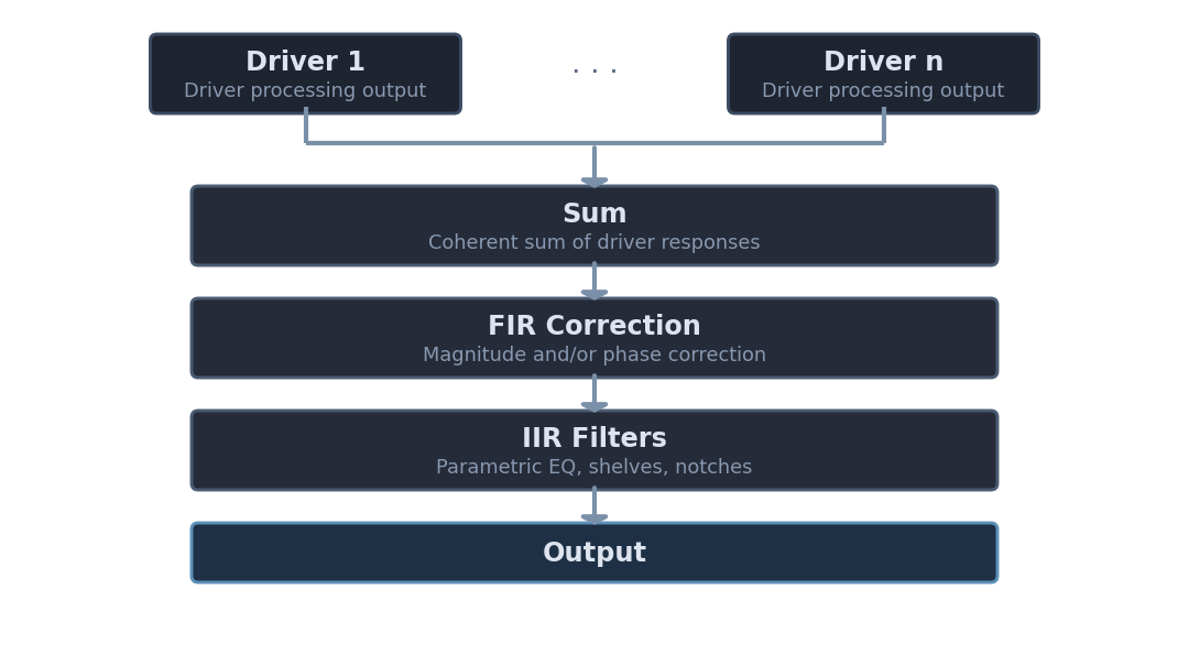
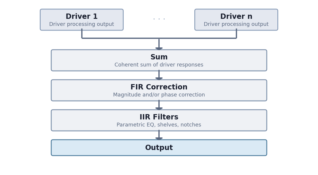
Loudspeaker Design
Driver responses are summed to form the combined system response before correction.
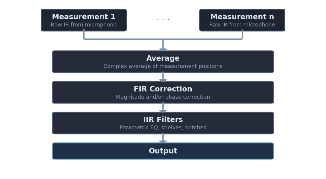
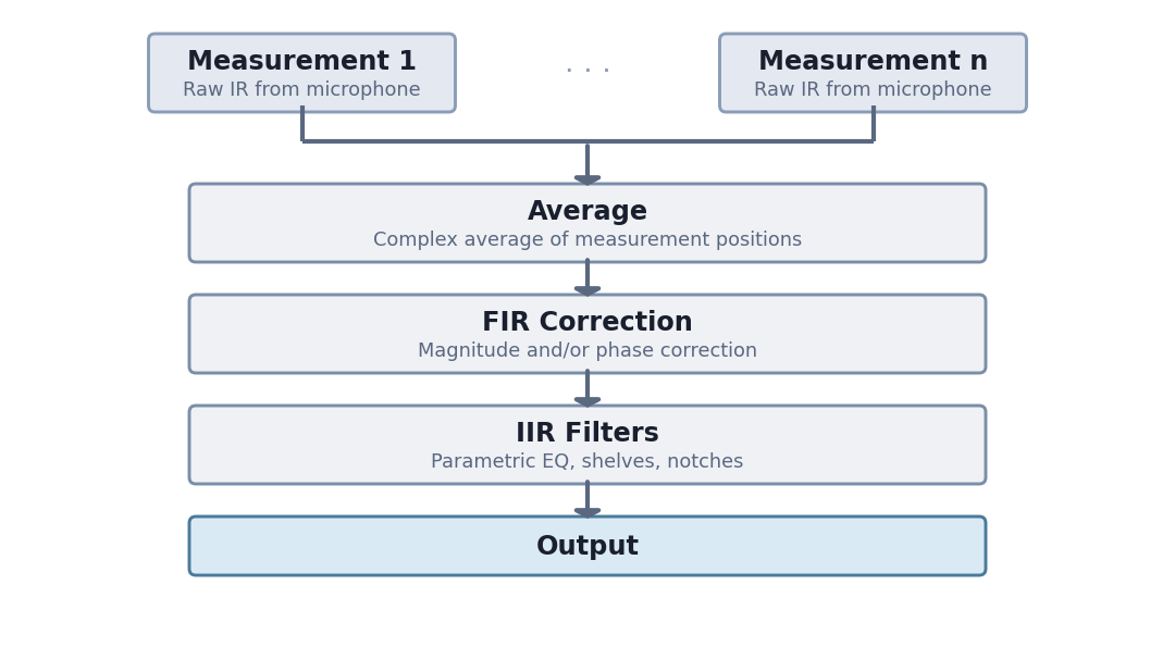
Room Calibration
Driver responses are averaged across measurement positions before correction.
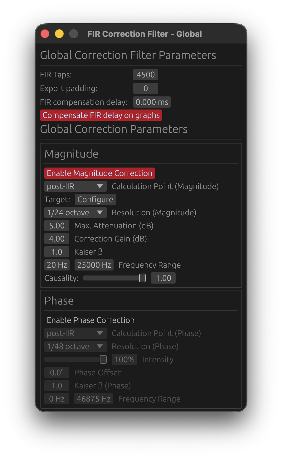
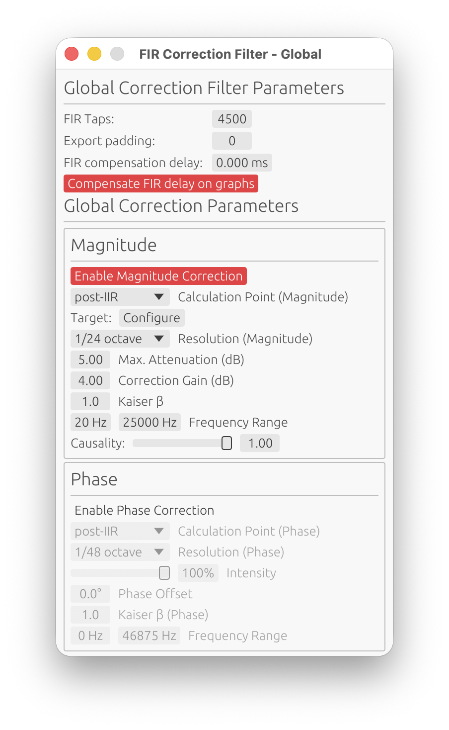
Global FIR Correction Filter
The Global FIR Correction Filter corrects the summed system response using FIR filters. It applies after all individual driver filters are combined, providing final system-level magnitude and phase correction.
Access the global FIR correction window from the Drivers/Measurements column (Global FIR button in the Global Filters section).
When to Use Global Correction
Loudspeaker Design Mode:
- Correct summed driver response/entire loudspeaker
- Align final system response to target curves (Flat, Harman, Custom)
- Compensate for baffle diffraction effects on the combined response
- Final system voicing and tuning
Room Calibration Mode:
- Room correction applied to the averaged measurements
- Correct combined room + speaker response
- Export global correction for integration into DSP processors
💡 Tip: Use global correction for overall tonal balance, and system-wide frequency response issues. Use per-driver correction (in Loudspeaker Design mode) for individual driver resonances, breakup modes, or response irregularities.
Global FIR Filter Length
FIR Taps
- Range: 32 to 65,536 taps
- Controls: the length (and thus frequency resolution) of the global FIR correction filter
How to choose:
- Higher tap counts → better low-frequency resolution, longer processing latency
- Lower tap counts → lower latency, reduced low-frequency precision
⚠️ Latency Note: The global FIR filter’s latency depends on tap count, magnitude causality, and phase correction:
- Causality = 1.0 (minimum-phase) + no phase correction: ~0 latency (impulse at t ≈ 0)
- Causality = 0.0 (linear-phase): ~
ntaps/2samples latency (impulse centered)- Phase correction enabled: adds latency regardless of causality (shifts impulse to center)
For low-latency applications, use Causality = 1.0 and disable phase correction.
Export Padding
- Range: 0 to 65,536 taps
- Purpose: Add zero-padding to the exported FIR filter files only
Export padding does not affect internal processing—it only extends the exported FIR coefficients with zeros. This is useful for:
- Meeting minimum FIR length requirements of external DSP platforms
- Aligning export formats across multiple filters
Example: If the global FIR filter is 4096 taps and you set export padding to 512, the exported file will contain 4608 coefficients (4096 actual + 512 zeros).
FIR Compensation Delay
- Range: -100 to +100 ms
- Purpose: Fine-tune the alignment of the global FIR filter in the processing chain
This parameter shifts the global FIR filter in time relative to the taps window.
Use Cases:
- Compensate for small timing misalignments introduced by FIR processing
- Adjust global FIR placement when mixing minimum-phase and linear-phase filters
💡 Tip: In most cases, leave this at 0 ms. Only adjust if you observe timing issues and ringing truncation in the impulse response.
Compensate FIR Delay on Graphs
- Toggle: Shift the impulse response left in plots to remove visual delay
When enabled:
- The impulse response plot shifts left by approximately
ntaps/2samples - The phase and group delay plots are also affected
- Exported filters are not modified
Purpose:
- Provides a clearer view of the aligned impulse response across drivers
- Useful for comparing driver responses without the visual offset from FIR latency
When to enable:
- When visually analyzing impulse alignment between drivers
- When comparing group delay and phase between the individual drivers and the sum
When to disable:
- When you need to see the true latency of the system
Magnitude Correction
The Magnitude Correction section corrects the frequency response (magnitude) of the summed system.
Enable Magnitude Correction
Toggle to enable/disable magnitude response correction independently from phase.
When disabled, magnitude correction settings are grayed out.
Reference (Magnitude)
- Options:
On-axisorListening Window - Default:
On-axis - Requires: A valid LinFIR license
Selects which response is used as input for computing the magnitude correction FIR filter.
On-axis:
- Uses the on-axis summed system response
- Standard behavior
Listening Window:
- Uses the spatial average of all polar measurements within ±30° horizontal and ±10° vertical as the correction input
- Corrects the tonal balance experienced across the listening zone, not just on-axis
- When selected, pre-IIR / post-IIR calculation point still applies normally
- Falls back to On-axis silently if fewer than 2 qualifying angles are available
💡 When to use Listening Window correction: When your listening position varies slightly off-axis (e.g., multiple listeners, wide seating arrangement), or when the speaker has significant directivity — the on-axis response may not be representative of what is actually heard. Correcting to a Listening Window average produces a more natural tonal balance across the sweet spot.
⚠️ Note: The Listening Window reference requires off-axis measurement data. Without at least 2 qualifying polar measurements, the option falls back to On-axis automatically.
Calculation Point (Magnitude)
- Options:
pre-IIRorpost-IIR - Purpose: Choose where to measure the system response for magnitude correction
pre-IIR:
- Measures the system before global IIR filters
- Corrects the summed driver response (FIR crossovers + driver FIR corrections + driver IIR)
- Use when you want to correct the raw driver summation before applying IIR EQ
post-IIR:
- Measures the system after global IIR filters
- Corrects the final system response (drivers + global IIR)
- Use for final system tuning or room correction that accounts for global IIR EQ
💡 Tip: For room calibration, use
post-IIRto correct the final room + speaker response. For loudspeaker design, usepre-IIRto correct driver interactions before applying global voicing EQ.
Target Curve
- Button:
Configure - Purpose: Select and configure the target curve for magnitude correction
Clicking Configure opens the Target Curve Window where you can:
- Select Flat or Harman as base curves
- Add inflection points and shape the curve
The magnitude correction FIR filter will match the response to this target curve.
See the Target Curves section in the documentation for details on curve types and customization.
Resolution (Magnitude)
- Options:
1/48 octave,1/24 octave,1/12 octave,1/6 octave,1/3 octave - Purpose: Control the smoothing applied to the magnitude correction
Lower fractions (e.g., 1/48 oct) → finer detail, corrects small ripples
Higher fractions (e.g., 1/3 oct) → broader smoothing, corrects only major trends
How to choose:
- Room correction: Use
1/6 octaveor1/3 octaveto avoid over-correcting room modes (which vary with position) - Loudspeaker design: Use
1/12 octaveor1/24 octavefor detailed driver correction
⚠️ Warning: Very fine smoothing (1/48 oct) can lead to excessive correction of measurement noise. Use with caution.
Max Attenuation
- Range: 0 to 30 dB
- Default: 10 dB
- Purpose: Limit the maximum attenuation (cut) applied by magnitude correction
This parameter “cuts from the top”—it limits how much the correction filter can reduce peaks in the frequency response.
Why limit attenuation?
- Prevents excessive cuts that waste headroom
- Avoids over-correcting narrow resonances (which may not be audible)
- Maintains system efficiency
Example:
- If the system has a +15 dB peak at 200 Hz and Max Attenuation is set to 10 dB, the correction will cut only 10 dB (leaving a +5 dB peak)
Recommended values:
- Room correction: 10–15 dB (room modes can be large)
- Loudspeaker design: 6–10 dB (driver peaks are typically smaller)
Correction Gain
- Range: -20 to +20 dB
- Default: 4 dB
- Purpose: Add gain to the correction filter to compensate for attenuation and maintain system level
Magnitude correction typically attenuates peaks, which reduces overall loudness. Correction Gain adds a fixed boost to restore the level.
How to choose:
- Set Correction Gain to approximately match the average attenuation applied
- For example, if the correction cuts ~4 dB on average, set Correction Gain to +4 dB
💡 Tip: Adjust Correction Gain by observing the final system level after correction. Too much gain can cause clipping or driver damage; too little leaves the system quieter than before.
Kaiser β (Magnitude)
Range: 0.0 to 50.0
Default: 8.0
Kaiser windowing parameter for the magnitude correction FIR filter.
Effect:
- Lower values (3-5): Sharper correction BUT may increase ringing
- Moderate values (6-10): Good balance between precision and ringing suppression
- Higher values (12-20): Smoother correction, reduced ringing, but less precise
Recommendation: Start with default 8.0, decrease to 1-2 if ringing is not problematic.
Frequency Range (Magnitude)
- f_min (minimum frequency): Starting point for magnitude correction
- f_max (maximum frequency): Ending point for magnitude correction
- Fade-in/Fade-out: Smooth transitions at the boundaries
Purpose: Limit magnitude correction to a specific frequency range.
Example:
- Set
f_min = 40 Hzandf_max = 12,000 Hzto correct only mid-bass through mid-treble, leaving deep bass and extreme treble unaffected
💡 Tip: Avoid correcting frequencies outside the measurement’s reliable range. Measurement noise dominates at the extremes.
Causality (Magnitude)
Range: 0.0 (linear-phase) to 1.0 (minimum-phase)
Default: 1.0 (minimum-phase)
Controls the phase characteristic of the magnitude correction filter.
- 0.0 (Linear-phase): Symmetric pre- and post-ringing, constant group delay
- 1.0 (Minimum-phase): No pre-ringing, all energy is causal, variable group delay
Typical choice: 1.0 (minimum-phase) to avoid pre-ringing artifacts.
Why minimum-phase is preferred: Most acoustic and electronic systems are minimum-phase (magnitude and phase are coupled via Kramers-Kronig relations). Correcting magnitude with a minimum-phase filter automatically corrects the associated phase deviation, providing physically accurate correction. Use 0.0 (linear-phase) only if you specifically need constant group delay with a non-flat target curve and can tolerate pre-ringing.
Phase Correction
The Phase Correction section corrects the group delay and phase response of the summed system.
Enable Phase Correction
Toggle to enable/disable phase response correction independently from magnitude.
🚫 Non-anechoic measurements: phase correction is strongly discouraged
Phase correction requires clean, accurate phase data. In-room measurements contain reflections, room modes, and position-dependent artifacts that pollute the phase response. Applying phase correction to such data produces unpredictable — and often worse — results.
Only use phase correction with anechoic or near-anechoic measurements (e.g., measurements gated to remove reflections, or made in an anechoic chamber). For in-room measurements, restrict correction to magnitude only.
Exception — Room Calibration mode with spatially averaged measurements: When the corrected response is the result of averaging several measurements taken at different listening positions, the influence of room modes and position-dependent reflections is drastically reduced. In this specific case, phase correction becomes more acceptable, as the averaged phase data is significantly less polluted than any single-point measurement.
Even so, spatial averaging is not a perfect substitute for anechoic conditions. A final verification measurement and critical listening session are recommended to confirm that no audible artifacts or regressions have been introduced by the phase correction.
⚠️ Critical Limitation: Phase Correction vs. Low Latency
You cannot have both near-zero latency FIR filters AND active phase correction. This is a fundamental limitation, not a software bug.
Why this incompatibility exists:
Even if you configure your FIR magnitude correction with causality = 1.0 (minimum-phase, low latency), which positions the FIR impulse peak near t=0 (left-aligned), enabling phase correction will shift the combined FIR impulse peak to the center (around ntaps/2), introducing significant latency.
The reason is fundamental:
- Phase correction = temporal correction: Phase distortion is fundamentally a time-domain problem (different frequencies arriving at different times)
- To correct temporal defects, you need time: The filter needs temporal “space” before and after the main impulse to reposition frequency components correctly
- This requires centering the impulse: Phase correction filters must have headroom both before (pre-ringing) and after (post-ringing) the main signal to perform time-domain manipulations
- Result: The combined FIR impulse peak moves from t≈0 (low latency) to t≈ntaps/2 (high latency)
Practical impact:
- Without phase correction: Causality=1.0 filters → impulse peak at t≈0 → latency ≈ 0 samples
- With phase correction enabled: Impulse peak moves towards t≈ntaps/2 → latency ≈ ntaps/2 samples (e.g., 2048 samples at 48kHz = 42.7ms)
Recommended approach:
- For low-latency applications (live sound, PA, monitoring): Use causality = 1.0 on crossover/magnitude filters, disable phase correction, accept phase as-is
- For high-fidelity applications (studio monitors, reference systems): Use causality = 0.0 on crossover, 1.0 on magnitude filters, enable phase correction if needed, accept the latency
- For hybrid approach: Use moderate causality (0.3-0.7) for reduced latency with some phase correction capability (but still expect significant latency when phase correction is active)
Calculation Point (Phase)
- Options:
pre-IIRorpost-IIR - Purpose: Choose where to measure the system response for phase correction
pre-IIR:
- Measures phase before global IIR filters
- Corrects driver phase interactions (crossover phase shifts, driver delays)
- Use when global IIR has minimal phase impact
post-IIR:
- Measures phase after global IIR filters
- Corrects final system phase (including IIR phase shifts)
- Use for complete system phase linearization
💡 Tip: Phase and magnitude correction can use different calculation points. For example, use
pre-IIRfor magnitude (correct drivers) andpost-IIRfor phase (linearize final system).
Resolution (Phase)
- Options:
1/48 octave,1/24 octave,1/12 octave,1/6 octave,1/3 octave - Purpose: Control the smoothing applied to phase correction
Same principle as magnitude resolution:
- Finer smoothing (1/48 oct) → corrects small phase variations
- Coarser smoothing (1/3 oct) → corrects only major phase trends
Recommended values:
- Room correction: 1/6 or 1/3 octave
- Loudspeaker design: 1/12 or 1/24 octave
Intensity
- Range: 0% to 100%
- Default: 100%
- Purpose: Control the strength of phase correction
100%: Full phase correction (matches measured phase to target)
0%: No phase correction
50%: Half-strength correction (blend between measured and target phase)
Use Cases:
- Reduce intensity (e.g., 70–80%) if full phase correction introduces audible artifacts
- Use partial correction to preserve some driver phase characteristics
💡 Tip: Start with 100% and reduce intensity if the correction sounds unnatural.
Phase Offset
Range: -180° to +180°
Default: 0°
Phase offset applied to the filter’s phase response.
Purpose: Controls the symmetry of the impulse response by adjusting the phase offset. This allows fine-tuning the balance between pre-ringing and post-ringing in the time-domain response.
How it works:
- 0°: Default even symmetric behavior
- Positive/Negative offset: Shifts impulse response characteristics towards odd symmetry
Use case: Advanced parameter for optimizing impulse response symmetry in multi-driver systems.
Recommendation: Leave at 0° unless you have specific symmetry requirements and understand impulse response trade-offs.
Kaiser β (Phase)
Range: 0.0 to 50.0
Default: 1.0
Kaiser windowing parameter for the phase correction FIR filter.
Effect:
- Lower values (1-5): Less aggressive windowing — the correction filter’s oscillations (pre- and post-ringing) are preserved more fully, allowing accurate phase correction
- Moderate values (6-10): Balanced windowing — trade-off between accuracy and artifact suppression
- Higher values (12-20): Aggressive windowing — strongly attenuates pre- and post-ringing, which can introduce magnitude deviations if correction energy is clipped
When to adjust:
- If the guard warning appears (the auto-guard has already narrowed the Start/End Frequencies as far as it can): decrease Kaiser β — see Phase Correction Magnitude Artifacts
- If phase correction creates excessive ringing, increase Kaiser β
Recommendation: Start with default 1.0. If the guard warning still appears after its automatic frequency adjustments, try reducing β toward 0.
Frequency Range (Phase)
- Start Frequency: Starting point for phase correction
- End Frequency: Ending point for phase correction
Purpose: Limit phase correction to a specific frequency range.
Use Cases:
- Avoid correcting phase at frequencies where group delay measurements are unreliable
- Avoid correcting phase outside speaker’s frequency response
- Reduce magnitude artifacts: low frequencies require the longest correction filters; the auto-correction guard raises the Start Frequency automatically when artifact warnings occur — see Phase Correction Magnitude Artifacts for a full explanation and resolution procedure
Global IIR Filtering
In addition to global FIR correction, LinFIR provides Global IIR Filters for system-wide parametric EQ.
When to Use Global IIR
- Room correction EQ: Parametric filters to address specific room modes
- Final system tuning: Overall tonal balance adjustments (bass/treble tilt, voicing)
- Low taps count: IIR filters require less processing power, allowing easier low end correction with small DSP processors
💡 Tip: Use global IIR for low end corrections and global FIR for high frequencies correction.
Access Global IIR Window
Access the global IIR window from the Drivers/Measurements column (Global IIR button in the Global Filters section).
Manual vs. Auto EQ Tabs
The Global IIR window has two tabs, identical to the per-driver IIR system:
Manual Tab:
- Manually add/edit parametric filters (PEQ, low shelf, high shelf, etc.)
- Full control over frequency, gain, Q
- Lock individual filters to prevent Auto EQ from modifying them
Auto EQ Tab:
- Automatically generates IIR filters to match the system to a target curve
- Same parameters as driver Auto EQ:
- Gain Offset: Adjust overall target level
- EQ Boost Cap: Prevent excessive boost
- Frequency range, Q range, Filter count
- Auto-generate toggle (requires license): see Auto-generate in the driver IIR documentation — same behaviour applies here; note that changing the target curve does not trigger auto-generation
Target curve overlay
When the Global IIR window is open and in the foreground with the Auto EQ tab selected, the configured target curve is displayed as a blue overlay directly on the frequency response graph. The curve is level-matched to the summed system response over the configured frequency range, and truncated to [Freq Min, Freq Max]. It disappears automatically when the window is sent to the background.
Auto EQ (Global)
Global Auto EQ works on the summed system response after driver processing:
- Measures the final system (drivers + global FIR + global IIR)
- Generates IIR filters to match the selected target curve (Flat, Harman, Custom)
- Applies to the entire system (not per-driver)
Reference
- Options:
On-axisorListening Window - Default:
On-axis - Requires: A valid LinFIR license
Selects which response is measured to generate the Auto EQ filters.
On-axis:
- Uses the on-axis summed system response
- Standard behavior
Listening Window:
- Uses the spatial average of all polar measurements within ±30°H / ±10°V as the response being equalized
- Optimizes the IIR filter shape to correct the Listening Window response towards the target curve
- The level reference (absolute dB anchor) is always taken from the on-axis response, regardless of this setting — this prevents a net gain offset from being introduced by the LW averaging
- Falls back to On-axis if fewer than 2 qualifying angles are available
💡 Tip: Using Listening Window for Auto EQ is particularly effective when the speaker has audible directivity variations within ±30°. The generated filters will address tonal imbalances that are present across the listening zone but may not be visible on the on-axis curve alone.
Use Cases:
- Room correction: Auto EQ generates filters to correct room + speaker response
- Final voicing: Quick tonal adjustments without regenerating FIR filters
Locked Filters (🔒):
Individual filters can be locked to preserve them during operations:
- Lock toggle: Click the 🔓/🔒 icon next to any filter to lock/unlock it
- Protected from Clear: Locked filters are not deleted when clicking “Clear Filters”
- Protected from Auto EQ: Locked filters are not removed when regenerating Auto EQ
- Integration into Auto EQ:
- locked filters are integrated into the Auto EQ target curve
- The optimizer respects their frequency response instead of trying to compensate
Use Cases:
- Set a protective high-pass filter, lock it, then let Auto EQ optimize the rest
- Lock a low-pass filter for driver protection while auto-correcting midrange
- Preserve manually tuned filters while regenerating Auto EQ corrections
- Combine manual protective filters with automatic room correction
Example Workflow:
- Switch to Auto EQ tab
- Add protective filters (e.g., -24 dB/oct HP at 60 Hz, room mode notches) using ➕ Add Filter
- Lock them using the 🔒 icon
- Configure target curve (Flat, Harman, Custom)
- Click “Generate” to run Auto EQ optimization
- Review and adjust: Edit any auto-generated filter directly (frequency, gain, Q)
- Lock refined filters: Lock manually adjusted filters to preserve them
- Iterate: Regenerate Auto EQ as many times as needed—locked filters stay in place
- Result: Auto EQ creates corrective filters while respecting locked protective filters
📖 For detailed Auto EQ parameter descriptions, see the Driver Processing page (Auto EQ section). Global Auto EQ uses identical parameters.
Workflow Recommendations
Loudspeaker Design Mode
- Design individual driver filters (FIR crossovers, FIR corrections, IIR EQ)
- Verify summed system response (check for phase cancellations, comb filtering)
- Apply global FIR correction if needed:
- Correct driver interaction issues (dips, peaks from crossover summing)
- Match system to target curve (Flat, Harman)
- Add global IIR filters for final voicing (bass/treble tilt, room-specific adjustments)
- Export filters for DSP platform
Room Calibration Mode
- Measure room response at listening position
- Apply global FIR correction:
- Set resolution to 1/6 or 1/3 octave (avoid over-correcting room modes)
- Limit frequency range (e.g., 500–18,000 Hz)
- Set Max Attenuation to 10–15 dB
- Add global IIR filters for specific room modes (parametric notches)
- Re-measure and iterate if needed
- Export global correction filters for room DSP processor
💡 Best Practice: In room calibration mode, avoid excessive correction of room modes and deep nulls. Boosting these regions by more than 6-10 dB risks clipping, increased distortion, driver overexcursion, and potential damage. Use acoustic treatment for problematic modes instead of EQ.
Related Documentation
- Driver Processing: Per-driver FIR/IIR filtering (loudspeaker design mode)
- Settings: Application-wide filter processing defaults
- Target Curves: Configuring Flat, Harman, and Custom curves
- Export: Exporting filters for DSP platforms (input FIR vs. output FIR)
Summary
Global FIR Correction provides system-level magnitude and phase correction for:
- Loudspeaker Design: Correcting summed driver interactions and final system voicing
- Room Calibration: Correcting room + speaker response at the listening position
Key Features:
- Independent magnitude and phase correction with separate calculation points (pre-IIR/post-IIR)
- Adjustable resolution, frequency range, and causality for flexible correction strategies
- FIR compensation delay and graph compensation for fine-tuning alignment and visualization
Global IIR Filtering complements FIR correction with:
- Manual parametric EQ for precise corrections
- Auto EQ for automatic target curve matching
- Locked filters for hybrid manual/automatic workflows
Use global processing after per-driver processing to achieve final system performance targets.