Distortion Impulse Responses 🔒
License Required: The Distortion IR window requires a valid LinFIR license.
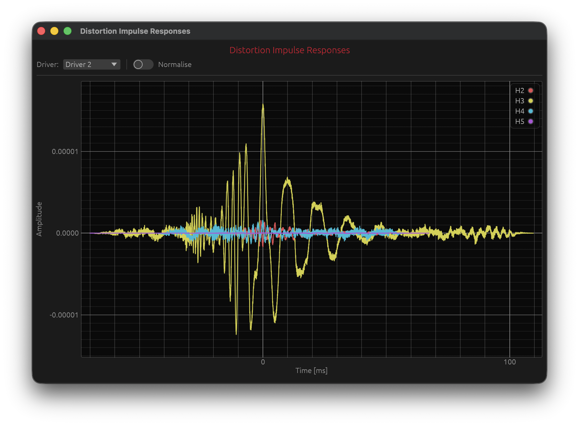
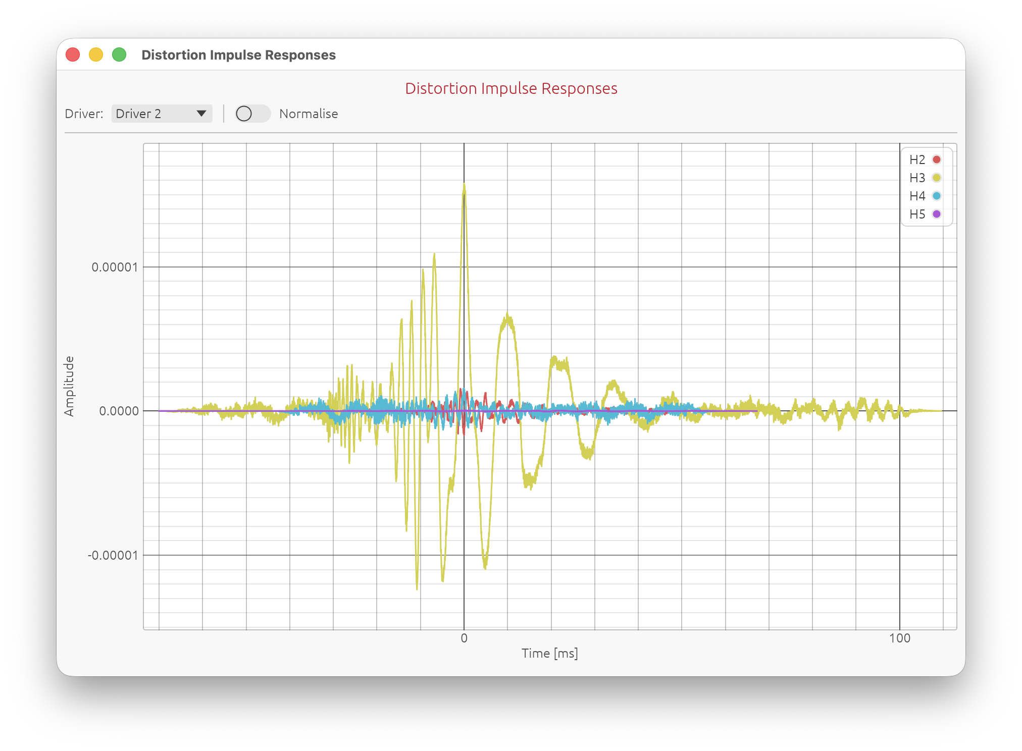
The Distortion IR window visualises the time-domain harmonic impulse responses (\(h_2\) through \(h_5\)) extracted from an ESS (Exponential Sine Sweep) Farina measurement. It shows the same windowed slices used to compute the THD spectrum.
Accessing the Distortion IR Window
Menu: View → Distortion IR
Keyboard shortcut: J
The window is available in Loudspeaker Design and Hypex FusionAmp modes, and requires that at least one driver has a valid ESS harmonic measurement.
What It Shows
When a driver is measured using the Sweep Measurements system (ESS method), LinFIR separates the harmonic components of the impulse response using the Farina deconvolution technique. Each harmonic order (k) arrives at a distinct, predictable time offset before the fundamental:
$$\Delta t_k = \frac{T_s \cdot \ln(k)}{\ln(f_2 / f_1)}$$
where \(f_1\), \(f_2\) are the sweep start and end frequencies and \(T_s\) the sweep duration.
The Distortion IR window displays these separated impulse response slices — \(h_2\), \(h_3\), \(h_4\), \(h_5\) — on a shared time axis, with all peaks aligned to the same time origin so the shape of each harmonic can be compared directly.
Angle Dependence
The displayed measurement follows the global angle selector. When a non-zero horizontal or vertical angle is selected, the window shows the harmonic impulse responses from the matching off-axis measurement (if one exists). The window title and header update to indicate the active angle, e.g.:
Distortion Impulse Responses — +15°H +0°V
If no measurement exists for the selected angle, the window automatically falls back to the on-axis (0°H 0°V) measurement.
Controls
Driver Selector
A ComboBox at the top of the control bar selects which driver’s harmonic slices are displayed.
Normalise
The Normalise toggle scales each harmonic curve independently so its peak amplitude equals 1.0. This makes the shape of each impulse response directly comparable regardless of the absolute distortion level.
With normalisation disabled, the amplitudes are proportional to the actual distortion levels.
Note: Normalise is a purely visual operation. It does not affect the underlying computation or the THD/distortion values in the main graphs.
Extraction and Windowing
Each harmonic slice is extracted as follows:
- Theoretical peak positions for \(h_2\)–\(h_{MAX}\) are computed from the ESS parameters.
- Cut points are located at the minimum of the smoothed Hilbert envelope between each pair of adjacent theoretical peaks, with a 5 % margin on each side to avoid touching either peak. This maximises the separation between harmonics and adapts automatically to any sweep duration or sample rate.
- Each slice is extracted between its two cut points — no overlap between adjacent harmonics.
- Sub-sample fractional delay correction is applied to align each harmonic to its exact theoretical position.
- Phase offset correction removes the constant phase bias introduced by the Farina deconvolution for each harmonic order.
- DC removal is applied.
- A 5 % raised-cosine fade-in / fade-out is applied to both ends of the slice before peak alignment. This windowing is independent for each harmonic and does not depend on the \(h_1\) IR window settings, because harmonic impulse responses can extend significantly further in time than the fundamental.
- All slices are zero-padded at the front so their peaks are aligned to a common time reference.
Distortion IR window shows the slices exactly as they enter the THD spectrum computation.
Requirements
- Driver must have an ESS sweep capture (exponential sine sweep measurement via Sweep Measurements).
- A valid LinFIR license is required to open the window.
Related Documentation
- Sweep Measurements — ESS measurement procedure and parameters
- Driver Processing — IR windowing for the fundamental \(h_1\)
- Spectrogram — time-frequency view of the full impulse response
- Directivity Analysis — off-axis frequency response visualisation
- License — license features and activation