Measurement Calibration
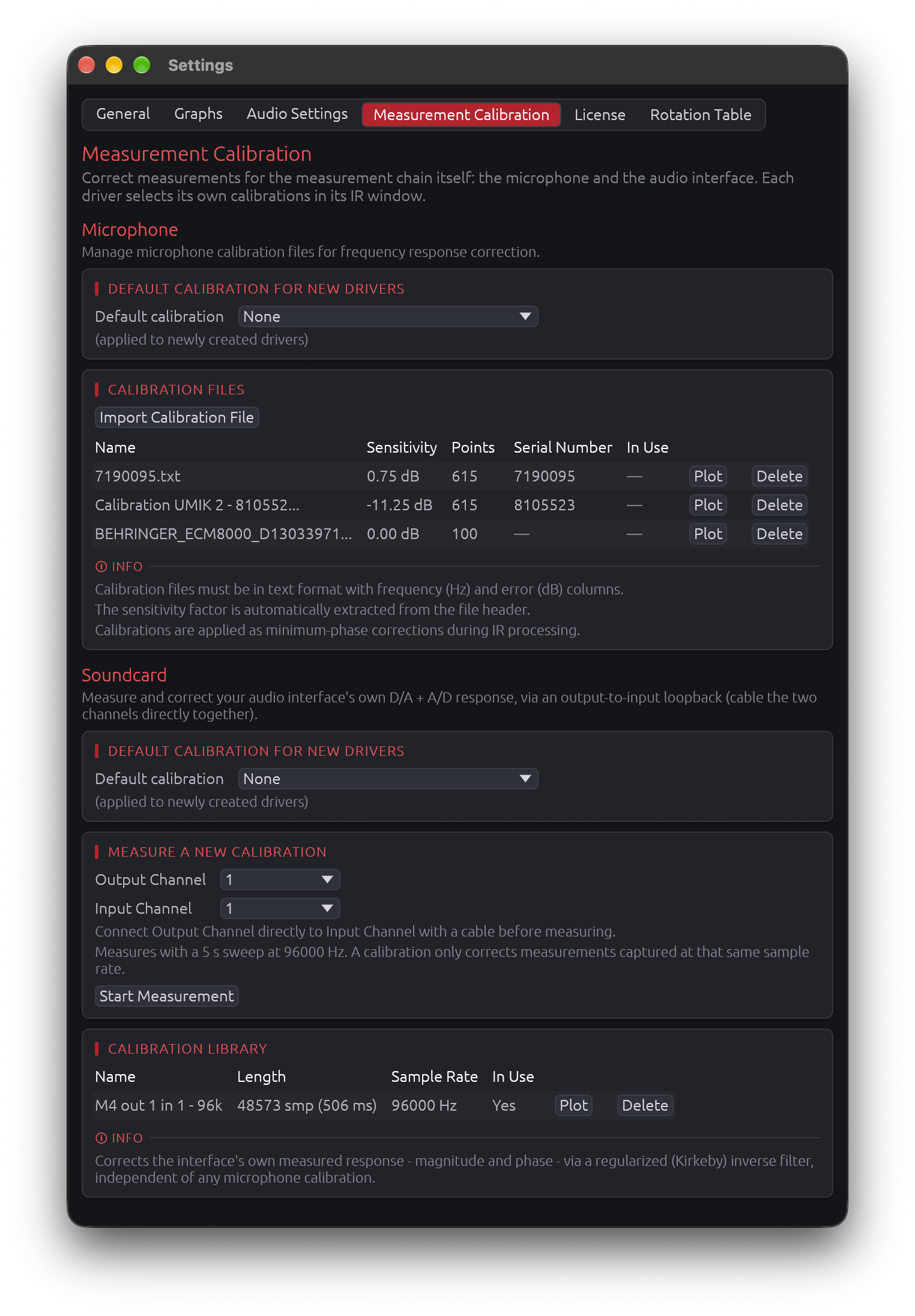
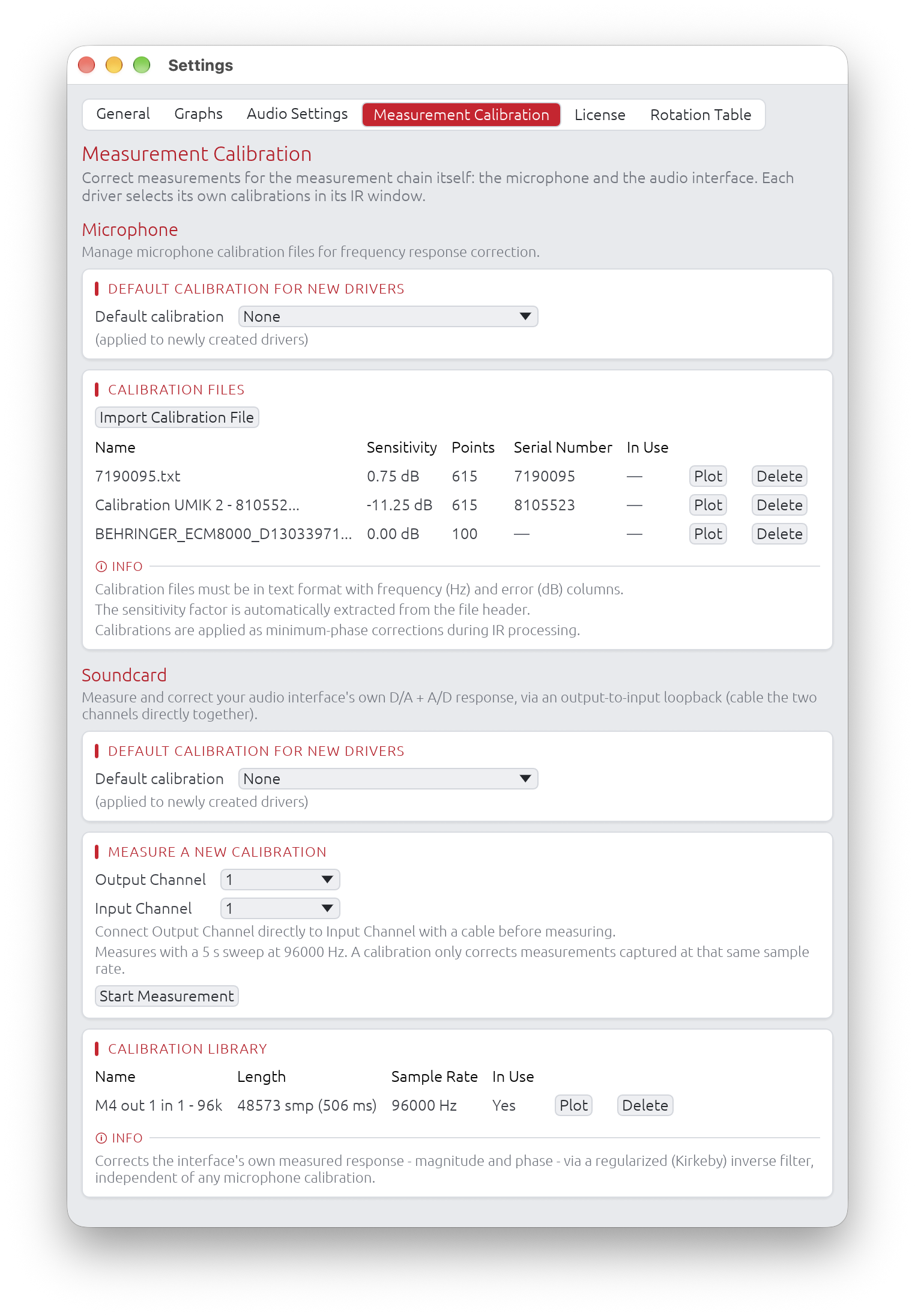
Correct measurements for the measurement chain itself, in two independent parts:
- Microphone: the measurement microphone’s frequency response and sensitivity, from its calibration file
- Soundcard: the audio interface’s own response, measured through a loopback cable
Each part keeps a library of calibrations in application settings, with a default for newly created drivers. Each driver then selects its own microphone and soundcard calibration (or none) in its IR window - see IR Management → Measurement Calibration.
Microphone
Manage calibration files for measurement microphones and define default calibrations for new drivers.
Overview
Microphone calibration compensates for the frequency response and sensitivity of your measurement microphone. LinFIR supports:
- Multiple calibration files stored in application settings
- Per-driver calibration selection in the IR Management window (see IR Management)
- Default calibration for newly created drivers
- Automatic application to new projects when a default is set
- Minimum-phase correction computed in real-time from calibration data
Calibration scope:
- Calibration data is embedded in project files (
.lnf) for portability - Calibrations from projects are also stored in application settings for reuse
- Each driver can use a different calibration file or none at all
Calibration File List
The main section displays all imported calibration files in a scrollable grid:
| Column | Content |
|---|---|
| Name | Calibration name, from the imported file (hover for the full name when truncated) |
| Sensitivity | Microphone sensitivity factor in dB |
| Points | Number of frequency/magnitude pairs in the file |
| Serial Number | Microphone serial number (if present in file), — otherwise |
| In Use | Yes if used in current project (hover to see driver names), — otherwise |
| Plot | Shows the calibration’s frequency response |
| Delete | Removes the calibration |
Automatic driver updates:
- When you delete a calibration file that’s currently assigned to one or more drivers, those drivers are automatically reset to “None”
- A warning toast will notify you which drivers were affected
- This prevents broken references and ensures project stability
Default Calibration
Select a calibration file to automatically apply to newly created drivers.
Dropdown selector:
- Shows “None” when no default is set
- Lists all imported calibration files by name
- Changes apply immediately to new drivers and projects
When the default is applied:
- Manual driver creation: When you add a new driver via the Drivers toolbar
- New Loudspeaker Design project: All initial drivers receive the default calibration
- New Room Calibration project: The initial measurement receives the default calibration
Note: Changing the default does not affect existing drivers in the current project or previously saved projects. Only new drivers created after the change receive the new default.
Import Calibration File
Click “Import Calibration File” to load a microphone calibration file.
Supported file format:
- Plain text files with two or three columns: Frequency (Hz), Magnitude (dB), and optionally Phase (degrees)
- Whitespace or comma-separated
- Lines starting with non-numeric characters are treated as comments/headers
- Optional header line with sensitivity factor and serial number
Note on phase column: If a third column (phase) is present, it is intentionally ignored. Phase data exported by calibration software is typically smoothed, wrapped, or otherwise processed in ways that make it unsuitable for direct use in transfer function reconstruction. Since measurement microphones exhibit predominantly minimum-phase behavior, reconstructing the phase from the magnitude alone (via Hilbert transform) is both accurate and more robust than relying on the exported phase values.
Example file format:
# Sens Factor = -2.5dB, SERNO: 41486651
# Frequency (Hz)  Magnitude (dB)
20.0              -0.5
50.0              -0.3
100.0             -0.1
200.0              0.0
500.0              0.1
1000.0             0.0
2000.0            -0.2
5000.0            -0.5
10000.0           -1.0
20000.0           -2.0
Sensitivity factor and serial number:
- Sensitivity factor (in dB) is automatically extracted from the file header if present (line containing “Sens Factor”)
- Serial number is automatically extracted if present (SERNO: field in header)
- If no sensitivity factor is found in the file, it defaults to 0 dB
- Serial number is used to differentiate calibrations with identical filenames when sharing projects
Storage:
Calibration data (frequency response, sensitivity, and serial number) is embedded in project files (.lnf) to ensure portability:
- Projects can be shared without requiring recipients to have the calibration files
- When loading a project, calibrations are automatically added to application settings if not already present
- If a calibration with the same name exists:
- With serial number: differentiated using serial number (e.g.,
filename (SN:7016078)) - Without serial number: differentiated using numeric suffix (e.g.,
filename (1),filename (2))
- With serial number: differentiated using serial number (e.g.,
- You can also manually import calibrations to your settings library for reuse across projects
How Calibration is Applied
Minimum-phase correction: LinFIR converts the imported frequency response correction into a minimum-phase FIR filter applied during IR processing.
Processing steps:
- Frequency filtering: Bins below 5 Hz are removed to prevent phase distortion at very low frequencies
- Interpolation: Calibration data is interpolated to match your IR’s sample rate and FFT size
- Minimum-phase conversion: Magnitude correction is converted to minimum-phase using Hilbert transform
- Sensitivity compensation: The sensitivity factor (dB) is applied as a gain adjustment
- IR application: The resulting correction filter is convolved with the driver’s impulse response
Phase behavior: LinFIR does not use phase data from calibration files, even when present. Instead, the correction filter’s phase is reconstructed from the magnitude response via the Hilbert transform (cepstral minimum-phase lifting). This is intentional:
- Phase columns in calibration files are typically smoothed, wrapped, or quantized by the calibration software, and directly applying such data would introduce artifacts.
- Measurement microphones exhibit predominantly minimum-phase behavior in their frequency response deviations, meaning the phase is largely determined by the magnitude — making reconstruction accurate without measured phase.
The resulting correction therefore affects both magnitude and phase of the measurement, with the phase derived from minimum-phase theory rather than read from the file.
Per-Driver Calibration Selection
Each driver can use a different calibration file (or none). To assign a calibration to a specific driver, use the Microphone dropdown of the Measurement Calibration section in the IR Management window.
See: IR Management → Measurement Calibration
Best Practices
File organization:
- Use descriptive filenames that include microphone model and serial number
- Example:
UMIK-1_SN123456.txtorEarthworks_M30_SN789.txt
Calibration maintenance:
- Import calibration files for all your measurement microphones
- Set your most frequently used microphone as the default
Project workflow:
- Assign calibrations in the IR Management window after importing measurements
- Use “None” for measurements taken with already-flat reference microphones
- Different drivers in the same project can use different calibrations (useful when combining measurements from multiple sessions)
Frequency range:
- Ensure calibration files cover the full measurement bandwidth
- LinFIR interpolates between provided points, but extrapolation beyond the calibration range may produce inaccurate results
- Most measurement microphones provide calibration data from 20 Hz to 20 kHz
Sensitivity factor:
- Use the value from your microphone’s calibration certificate
- This is typically a negative dB value (e.g., -0.5 dB, -2.4 dB)
- If unsure, use 0 dB and rely solely on the frequency response correction
Soundcard
Measure your audio interface’s own response once, and remove it from every measurement taken through it.
Overview
An audio interface is not perfectly transparent: its converters and their filters shape the magnitude and phase of everything you measure, mostly at the frequency extremes (phase rotation in the low bass, roll-off and phase shift near Nyquist). A soundcard calibration measures that response through an output-to-input loopback cable and corrects it with a regularized (Kirkeby) inverse filter:
- Magnitude and phase are both corrected, from the measured response itself
- Timing is preserved: the corrected impulse response stays where it was, so window positions and delays are unaffected
- Overall level is unchanged: only the response’s shape is corrected
- Correction range follows the sweep the calibration was measured with; outside it, measurements are left untouched
- Independent of the microphone calibration: a driver can use either, both, or neither
Default Calibration
Select a calibration to automatically assign to newly created drivers. As for microphones, changing the default does not affect existing drivers.
Measure a New Calibration
- Connect the Output Channel directly to the Input Channel with a cable - no amplifier, no microphone
- Select both channels, then click Start Measurement
- When the measurement completes, give it a Name and click Save (or Discard)
The measurement uses a 5 s sweep at the sample rate currently set in Audio Settings.
Sample rate matters. A soundcard calibration only corrects measurements captured at the sample rate it was measured at: an interface’s response changes from one sample rate to another, so a calibration is never resampled. Measure one calibration per sample rate you work at. In a driver’s IR window, calibrations measured at another sample rate than the driver’s measurements are greyed out, and a warning is shown if the selected one doesn’t match.
Calibration Library
| Column | Content |
|---|---|
| Name | Name given when saving the measurement |
| Length | Impulse response length, in samples and milliseconds |
| Sample Rate | Sample rate the calibration was measured at |
| In Use | Yes if used in the current project (hover to see driver names) |
| Plot | Shows the calibration’s frequency response |
| Delete | Removes the calibration; drivers using it are reset to “None”, with a warning |
Storage: like microphone calibrations, soundcard calibrations are embedded in project files and added to application settings when a project is loaded.
How the Correction is Applied
- Applied to every measurement of the driver, on its impulse response (or its near-field / far-field spliced response) before the time window
- Computed once per measurement and reused: changing the window or other settings doesn’t recompute it
- Harmonic distortion is analyzed on the uncorrected capture, since a correction would shift the harmonics’ positions; the calibration is then applied as a gain to the fundamental and to each harmonic at its own frequency
Best Practices
- Measure through the same interface, channels, and sample rate as your driver measurements
- Measure again after changing the interface, its routing, or the sample rate you work at
- On a loopback, the interface’s own distortion is part of both the measurement and the calibration: interpret the THD of a loopback measurement with care